12.95
6.1 Single I/O module
6-92
E Siemens AG, 2002. All rights reserved
SINUMERIK 810D Manual Hardware Configuration (PHC) -- 11.02 Edition
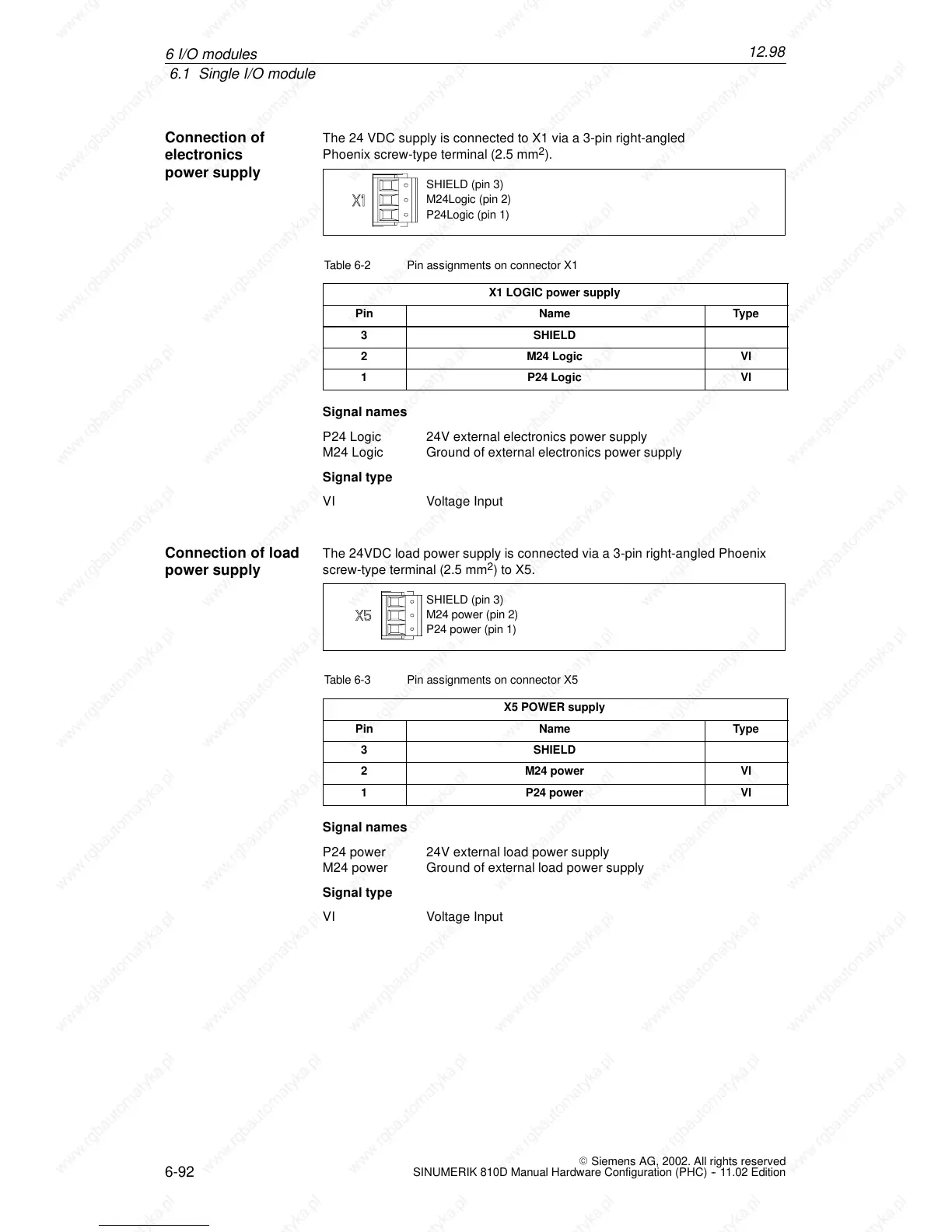
The 24 VDC supply is connected to X1 via a 3-pin right-angled
Phoenix screw-type terminal (2.5 mm
2
).
P24Logic (pin 1)
M24Logic (pin 2)
SHIELD (pin 3)
Table 6-2 Pin assignments on connector X1
X1 LOGIC power supply
Pin Name Type
3 SHIELD
2 M24 Logic VI
1 P24 Logic VI
Signal names
P24 Logic 24V external electronics power supply
M24 Logic Ground of external electronics power supply
Signal type
VI Voltage Input
The 24VDC load power supply is connected via a 3-pin right-angled Phoenix
screw-type terminal (2.5 mm
2
)toX5.
P24 power (pin 1)
M24 power (pin 2)
SHIELD (pin 3)
Table 6-3 Pin assignments on connector X5
X5 POWER supply
Pin Name Type
3 SHIELD
2 M24 power VI
1 P24 power VI
Signal names
P24 power 24V external load power supply
M24 power Ground of external load power supply
Signal type
VI Voltage Input
Connection of
electronics
power supply
Connection of load
power supply
6I
 Loading...


