12.95
6.1 Single I/O module
6-95
E Siemens AG, 2002. All rights reserved
SINUMERIK 810D Manual Hardware Configuration (PHC) -- 11.02 Edition
27
INP70
I 28
INP71
I
29
INP72
I 30
INP73
I
31
INP74
I 32
INP75
I
33
INP76
I 34
INP77
I
Signal names
INPiξjζ Input j of input byte i
Signal type
I Input
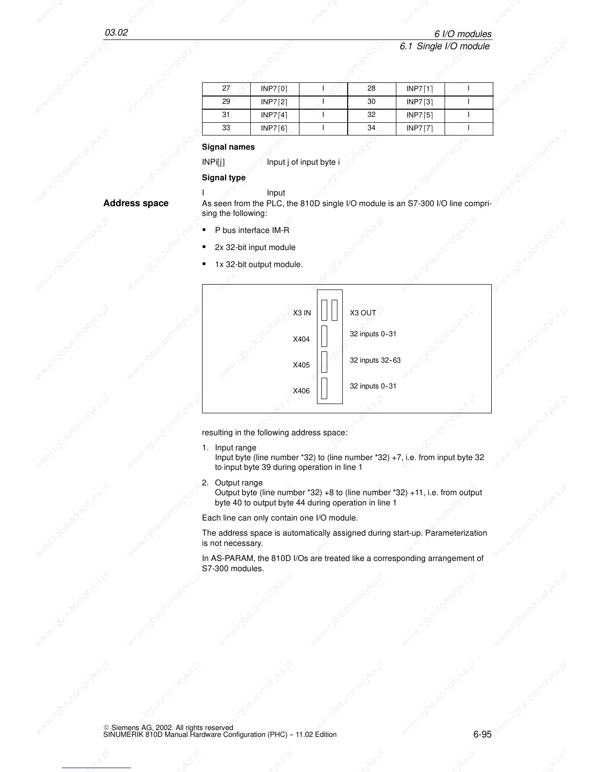
As seen from the PLC, the 810D single I/O module is an S7-300 I/O line compri-
sing the following:
S P bus interface IM-R
S 2x 32-bit input module
S 1x 32-bit output module.
X404
X405
X406
X3 IN X3 OUT
32 inputs 0--31
32 inputs 32--63
32 inputs 0--31
resulting in the following address space:
1. Input range
Input byte (line number *32) to (line number *32) +7, i.e. from input byte 32
to input byte 39 during operation in line 1
2. Output range
Output byte (line number *32) +8 to (line number *32) +11, i.e. from output
byte 40 to output byte 44 during operation in line 1
Each line can only contain one I/O module.
The address space is automatically assigned during start-up. Parameterization
is not necessary.
In AS-PARAM, the 810D I/Os are treated like a corresponding arrangement of
S7-300 modules.
Address space
6I
 Loading...


