X1, X2: Ethernet interfaces
The pin assignment of the Ethernet interfaces X1 and X2 can be found in the Chapter:
"Connecting", Section: "Pin assignment of the interfaces (Page 26)".
X3: Power supply
For the pin assignments of the power supply interface X3, refer to Chapter: "Connecting",
Section: "Pin assignment of the interfaces (Page 26)".
X7: Panel Present
Connector designa‐
tion:
X7
Connector type: 6-pin Phoenix terminal
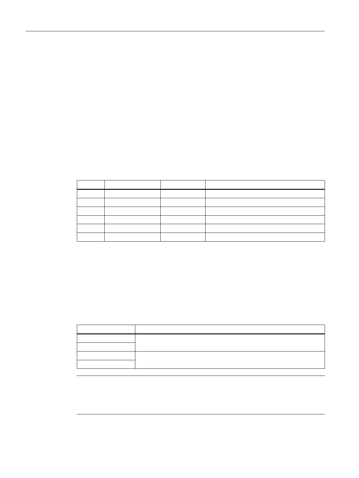
Table 4-3 Assignment of the interface Panel Present X7
Pin Signal name Signal type Meaning
1 PRES O "High": Panel (HT 10) inserted
2 XCTL O "Low": EMER STOP button pressed
1)
3 XFAULT O "Low": Error in emergency stop electronics
1)
4 N.C. - Not connected
5 N.C. - Not connected
6 M P Ground
1)
Function not implemented in Basic PN variant, output is not switched to "High"
X8: Emergency Stop wiring terminal
Connector designa‐
tion:
X8
Connector type: 4-pin Phoenix terminal
Table 4-4 Assignment of the emergency stop wiring terminal X8
Pin Protective circuit
1 On-board jumper
between 1 and 2
2
3 On-board jumper
between 3 and 4
4
Note
Use this terminal for simple routing of the emergency stop cables, optional.
The connector is only used to assist looping through. The connected pins 1 and 2 as well as 3 and
4 have no additional function on the connection module.
Connecting
4.5 PN Basic connection module
Handheld Terminal HT 10
56 Equipment Manual, 09/2020, A5E47430965B AA

 Loading...


