X20: Enabling buttons
Connector designa‐
tion:
X20
Connector type: 8-pin Phoenix terminal
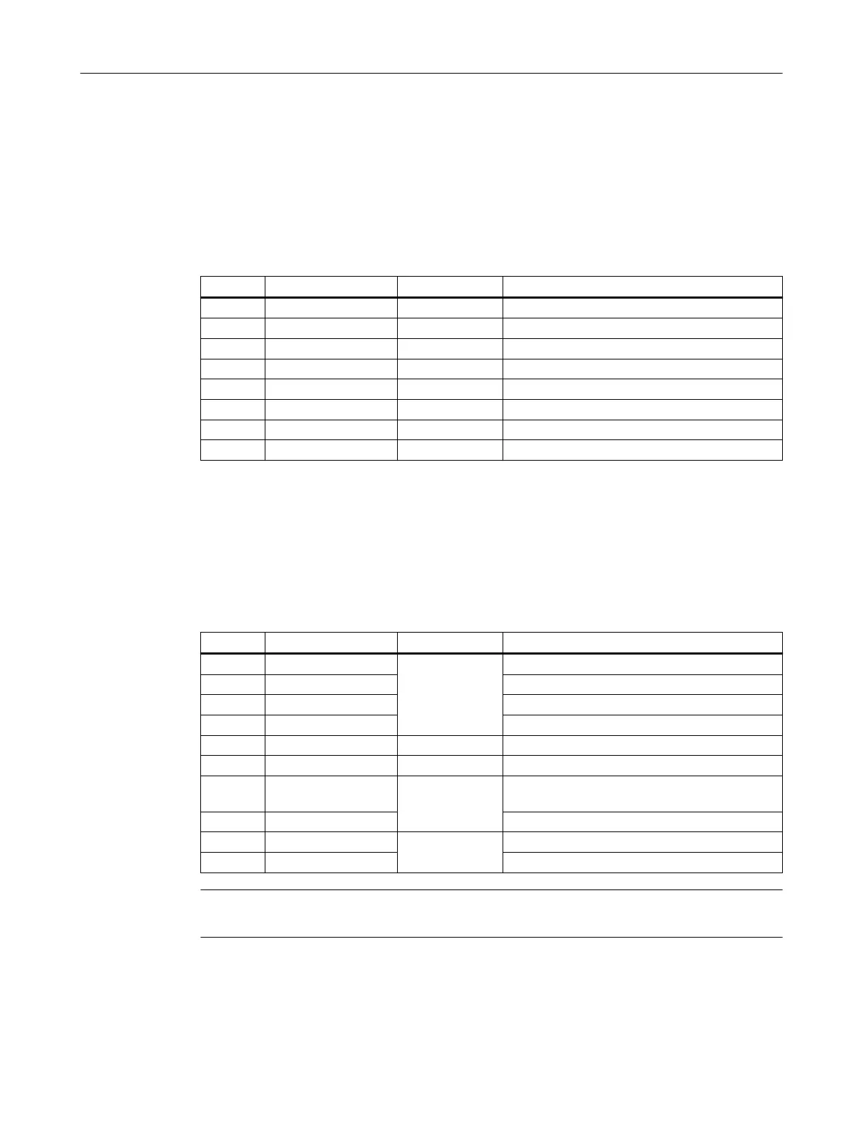
Table 4-5 Assignment of the interface enabling buttons X20
Pin Signal name Signal type Meaning
1 ZUST1P I Enabling button 1 P
2 ZUST1M O Enabling button 1 M
3 ZUST2P I Enabling button 2 P
4 ZUST2M O Enabling button 2 M
5 N.C. - Not connected
6 N.C. - Not connected
7 N.C. - Not connected
8 N.C. - Not connected
X21: Emergency Stop and key-operated switch
Connector designa‐
tion:
X21
Connector type: 10-pin Phoenix terminal
Table 4-6 Assignment of the interface Emergency Stop and Module Supply Voltage
Pin Signal name Signal type Meaning
1 STOP23
B
Emergency Stop circuit
2 STOP24 Emergency Stop circuit
3 STOP13 Emergency Stop circuit
4 STOP14 Emergency Stop circuit
5 M P Ground
6 N.C. - -
7 IN_E9
P
Connected P24 (jumpered to Pin8 during opera‐
tion)
8 P24_FILT Filtered 24 V module power supply
9 IN_E9_EXT
O
Feedback signal via connected P24
10 IN_E12_EXT "High": Terminating connector plugged in
Note
Pins 7 and 8 must be jumpered in order to supply a handheld terminal with power.
Connecting
4.5 PN Basic connection module
Handheld Terminal HT 10
Equipment Manual, 09/2020, A5E47430965B AA 57

 Loading...


