Mounting and Commissioning
3.2 Checking Connections
SIPROTEC, 7RW80, Manual
C53000-G1140-C233-1, Release date 10.2010
157
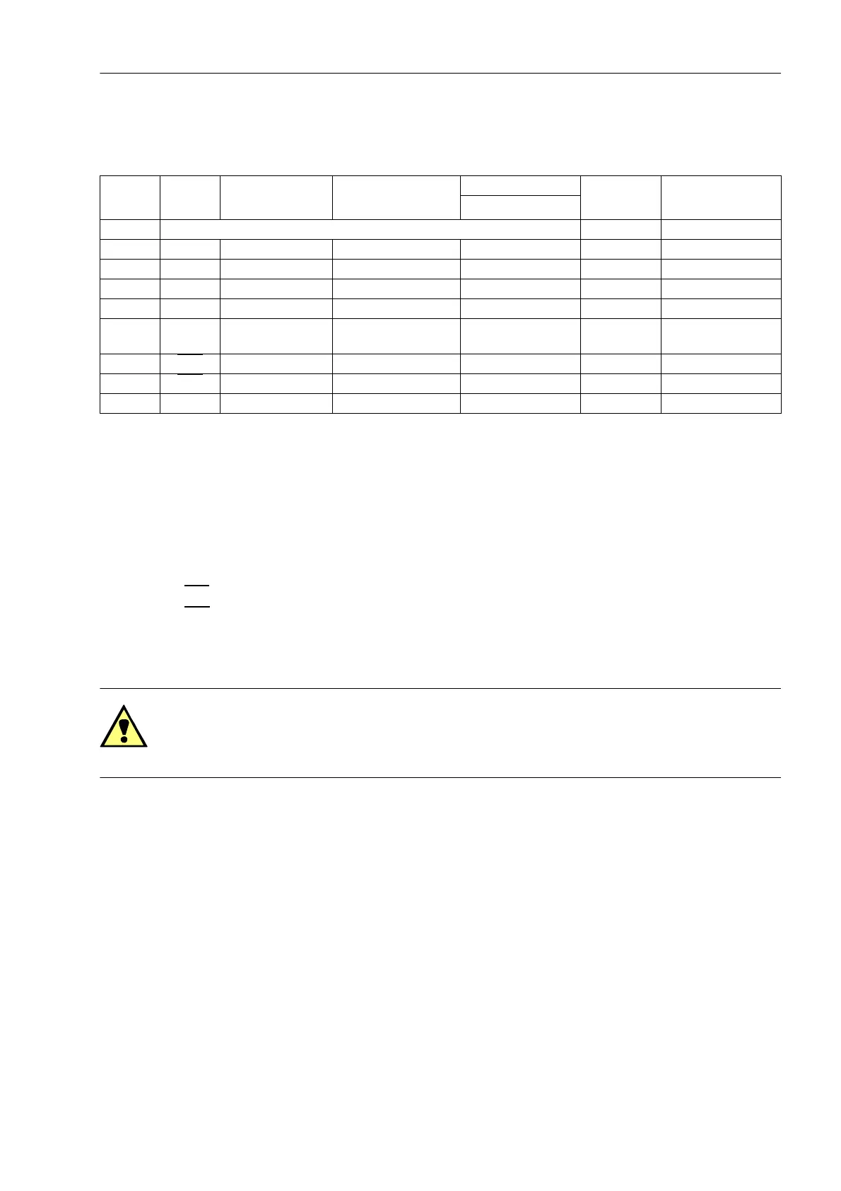
Connections at port B
Table 3-4 Assignment of the port B sockets
1)
Pin 7 also carries the RTS signal with RS232 level when operated as RS485 interface. Pin 7 must therefore not be con-
nected!
With data cables, the connections are designated according to DIN 66020 and ISO 2110:
• TxD = Data output
• RxD = Data input
•RTS
= Request to send
•CTS
= Clear to send
• GND = Signal/Chassis Ground
Fiber-optic Cables
WARNING!
Laser Radiation!
Do not look directly into the fiber-optic elements!
Signals transmitted via optical fibers are unaffected by interference. The fibers guarantee electrical isolation
between the connections. Transmit and receive connections are represented by symbols.
The standard setting of the character idle state for the optical fiber interface is „Light off“. If the character idle
state is to be changed, use the operating program DIGSI as described in the SIPROTEC 4 System Description.
Pin No. RS232 RS485 Profibus DP, RS485 Modbus RS485 Ethernet
EN 100
IEC 60870–5–103
redundant
DNP3.0 RS485
1 Shield (electrically connected with shield shroud) Tx+ B/B’ (RxD/TxD-P)
2 RxD – – – Tx– A/A’ (RxD/TxD-N)
3 TxD A/A’ (RxD/TxD-N) B/B’ (RxD/TxD-P) A Rx+ –
4 – – CNTR-A (TTL) RTS (TTL level) — –
5 GND C/C' (GND) C/C' (GND) GND1 — –
6 – – +5 V (max. load <100
mA)
VCC1 Rx– –
7RTS
–
1)
––—–
8CTS
B/B’ (RxD/TxD-P) A/A’ (RxD/TxD-N) B — –
9 – – – – not available not available

 Loading...


