Functions
2.3 Directional Overcurrent Protection 67, 67N
SIPROTEC, 7SJ62/64, Manual
C53000-G1140-C207-2, Release date 01.2008
105
Direction Determination with Zero-sequence System or Ground Quantities
For the directional ground fault elements, direction can be determined by comparing the zero-sequence system
quantities. In the current path, the I
N
current is valid, when the transformer neutral current is connected to the
device. Otherwise the device calculates the ground current from the sum of the three phase currents. In the
voltage path, the displacement voltage V
N
is used as reference voltage, if it is connected. Otherwise the device
calculates as reference voltage the zero-sequence voltage 3 · V
0
from the sum of the three phase voltages. If
the magnitude of V
0
or 3 · V
0
is not sufficient to determine direction, the direction is undefined. Then the direc-
tional ground elements will not initiate a trip signal. If the current I
0
cannot be determined, e.g. because only
two current transformers are utilized or the current transformers are connected in an open delta configuration,
then the directional ground elements will not be able to function. The latter is only permitted in ungrounded sys-
tems.
Direction Determination with Negative Sequence System
Here, the negative sequence current and as reference voltage the negative sequence voltage are used for the
direction determination. This is advantageous if the zero sequence is influenced via a parallel line or if the zero
voltage becomes very small due to unfavorable zero impedances. The negative sequence system is calculated
from the individual voltages and currents. As with the use of the zero sequence values, a direction determina-
tion is carried out if the values necessary for the direction determination have exceeded a minimum threshold.
Otherwise the direction is undetermined.
Cross-Polarized Reference Voltages for Direction Determination
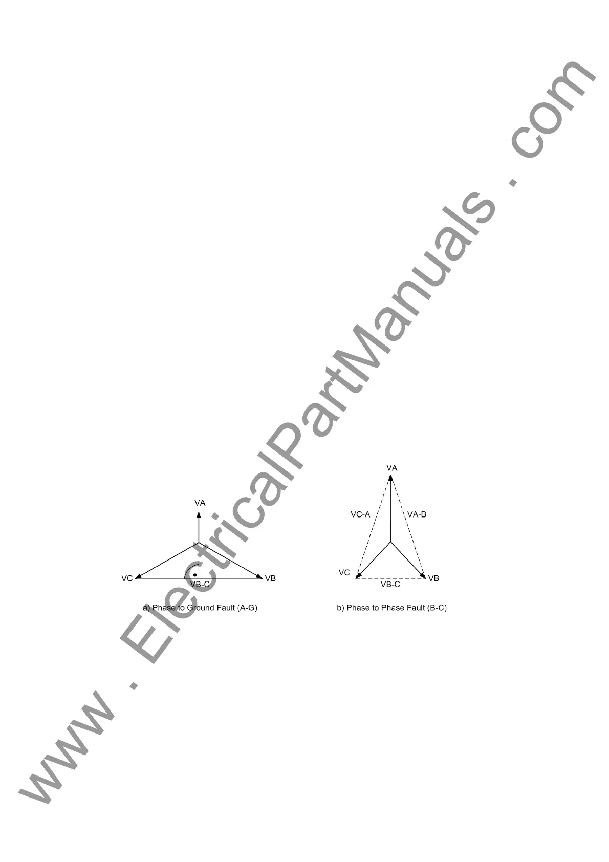
The direction of a phase-directional element is detected by means of a cross-polarized voltage. In a phase-to-
ground fault, the cross-polarized voltage (reference voltage) is 90° out of phase with the fault voltages (see
Figure 2-26). With phase-to-phase faults, the angle between the cross-polarized voltages (reference voltages)
and the fault voltages can be between 90° (remote fault) and 60° (local fault) depending on the degree of col-
lapse of the fault voltages.
Figure 2-26 Cross-polarized voltages for direction determination
The phase carrying the highest current is selected for the direction decision. With equal current levels, the
phase with the smaller number is chosen (I
A
before I
B
before I
C
). The following table shows the allocation of
measured values for the determination of fault direction for various types of pickups for the phase element.
www . ElectricalPartManuals . com

 Loading...


