Functions
2.12 Ground Fault Protection 64, 67N(s), 50N(s), 51N(s)
SIPROTEC, 7SJ62/64, Manual
C53000-G1140-C207-2, Release date 01.2008
220
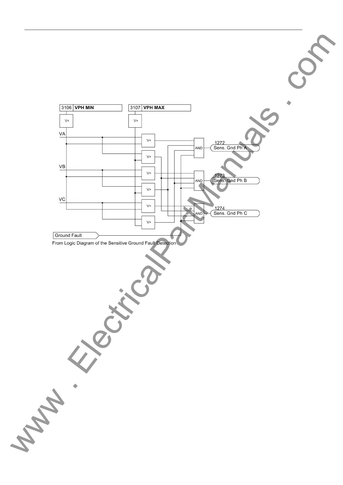
After the voltage element picks up due to detection of a displacement voltage, the grounded phase is identified,
if possible. To do this, the individual phase-to-ground voltages are measured. Of course, this is only possible if
three phase-to-ground voltages are obtained from voltage transformers connected in a grounded wye config-
uration. If the voltage magnitude for any given phase is below the setting value V
Ph min
, that phase is detected
as the grounded phase as long as the remaining phase-to-ground voltages are simultaneously above the
setting value V
Ph max
.
Figure 2-76 Determination of Grounded Phase
Current Elements
The current elements for ground faults operate with the magnitudes of the ground current. It is sensible to
employ them only where the magnitude of the ground current can be used to specify the ground fault. This may
be the case on grounded systems (solid or low-resistance) or on electrical machines which are directly con-
nected to the busbar of an isolated power system, when in case of a network ground fault the machine supplies
only a negligible ground fault current across the measurement location, which must be situated between the
machine terminals and the network, whereas in case of a machine ground fault the higher ground fault current
produced by the total network is available. Ground current protection is mostly used as backup protection for
high resistance ground faults in solid or low resistance grounded systems when the main fault protection does
not pickup.
For ground current detection, a two-element current/time characteristic can be set. Analog to the overcurrent
protection, the high-set current element is designated as 50Ns-2 PICKUP and 50Ns-2 DELAY and is provid-
ed with a definite time characteristic. The overcurrent element may be operated with either a definite time delay
(50Ns-1 PICKUP and 50Ns-1 DELAY) or with a user-defined characteristic (51Ns PICKUP and 51NsTIME
DIAL). Additionally, a current element with logarithmic inverse characteristic or logarithmic inverse character-
istic with knee point is implemented. The characteristics of these current elements can be configured. Each of
these elements may be directional or non-directional.
The pickup of the definite time overcurrent protection can be stabilized by the configured dropout delay time
(address 3121 50Ns T DROP-OUT).
www . ElectricalPartManuals . com

 Loading...


