Functions
2.12 Ground Fault Protection 64, 67N(s), 50N(s), 51N(s)
SIPROTEC, 7SJ62/64, Manual
C53000-G1140-C207-2, Release date 01.2008
221
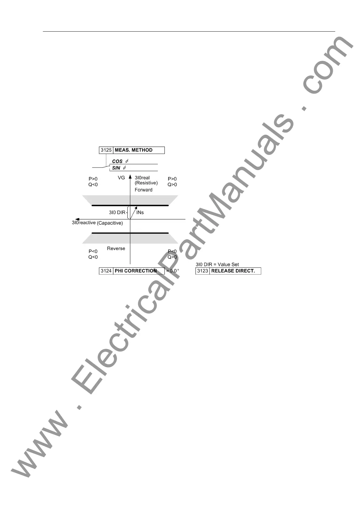
Determination of Direction
When determining the sensitive ground fault direction it is not the current value that is crucial, but the part of
the current which is perpendicular to a settable directional characteristic (axis of symmetry). As a prerequisite
for determining the direction, the displacement voltage V
0
must be exceeded as well as a configurable current
part influencing the direction (active or reactive component).
The following figure illustrates an example using a complex vector diagram in which the displacement voltage
V
0
is the reference magnitude of the real axis. The active part 3I0
real
of current 3I
0
is calculated with reference
to the displacement voltage V
0
and compared with setting value RELEASE DIRECT.. The example is therefore
suitable for ground fault direction in grounded systems where quantity 3I
0
· cos ϕ is relevant. The directional
limit lines are perpendicular to axis 3I0
real
.
Figure 2-77 Directional characteristic for cos–ϕ–measurement
The directional limit lines may be rotated by a correction angle (address PHI CORRECTION) up to ± 45°. There-
fore, in grounded systems it is possible e.g. to increase sensitivity in the resistive-inductive range with a rotation
of –45°, or in case of electric machines in busbar connection in the resistive-capacitive range with a rotation of
+45° (see the following Figure). Furthermore the directional limit lines may be rotated by 90° to determine
ground faults and their direction in grounded systems.
www . ElectricalPartManuals . com

 Loading...


