Mounting and Commissioning
3.2 Checking Connections
SIPROTEC, 7SJ62/64, Manual
C53000-G1140-C207-2, Release date 01.2008
440
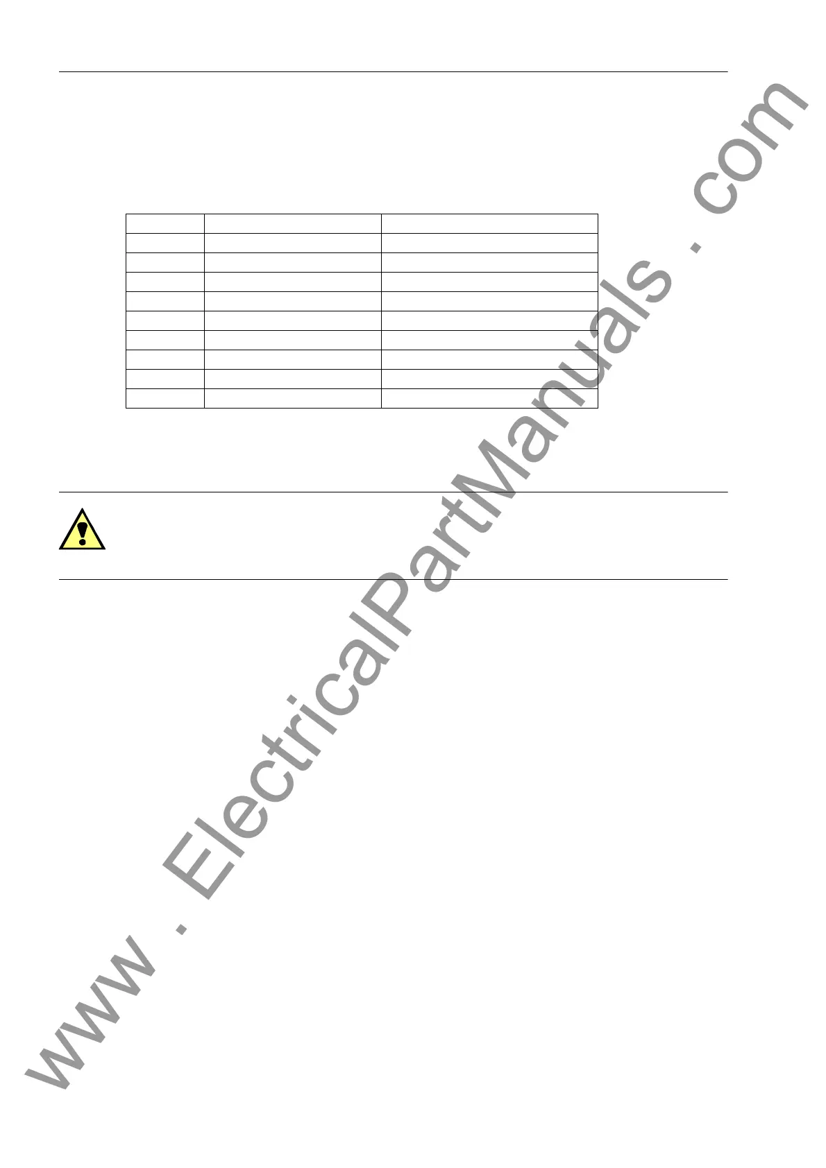
Time Synchronization Interface
It is optionally possible to process 5 V-, 12 V- or 24 V- time synchronization signals, provided that they are
carried to the inputs named in the following table.
Table 3-32 D-SUB socket assignment of the time synchronization interface
1)
assigned, but not used
Fiber-optic Cables
WARNING!
Laser Radiation!
Do not look directly into the fiber-optic elements!
Signals transmitted via optical fibers are unaffected by interference. The fibers guarantee electrical isolation
between the connections. Transmit and receive connections are represented by symbols.
The standard setting of the character idle state for the optical fiber interface is „Light off“. If the character idle
state is to be changed, use the operating program DIGSI as described in the SIPROTEC 4 System Description.
Temperature Detection Unit (RTD Box)
If one or two 7XV5662-xAD temperature detection units are connected, check their connections to the port (port
C or D).
Verify also the termination: The terminating resistors must be connected to 7SJ62/64 (see margin heading „Ter-
mination“).
For further information refer to the operating manual of 7XV5662-xAD. Check the transmission settings at the
temperature meter. Besides the baud rate and the parity the bus number is also important.
For connection of RTD-box(es) proceed as follows:
• For connection of 1 RTD box 7XV5662-xAD: Bus number = 0 (to be set on 7XV5662-xAD).
• For the connection of 2 RTD boxes 7XV5662-xAD: bus number = 1 for the 1st RTD box (to be set on
7XV5662–xAD for RTD 1 to 6), bus number = 2 for the 2nd RTD box (to be set on 7XV5662-xAD for RTD 7
to 12).
Please observe that detector input 1 (RTD1) of the first RTD-box is assigned for ambient or coolant temperature
of the overload protection.
Pin No. Description Signal Meaning
1 P24_TSIG Input 24 V
2 P5_TSIG Input 5 V
3 M_TSIG Return Line
4–
1)
–
1)
5 SHIELD Shield Potential
6– –
7 P12_TSIG Input 12 V
8 P_TSYNC
1)
Input 24 V
1)
9 SHIELD Shield Potential
www . ElectricalPartManuals . com

 Loading...


