42
SIVACON S8 Planning Principles – Universal mounting design
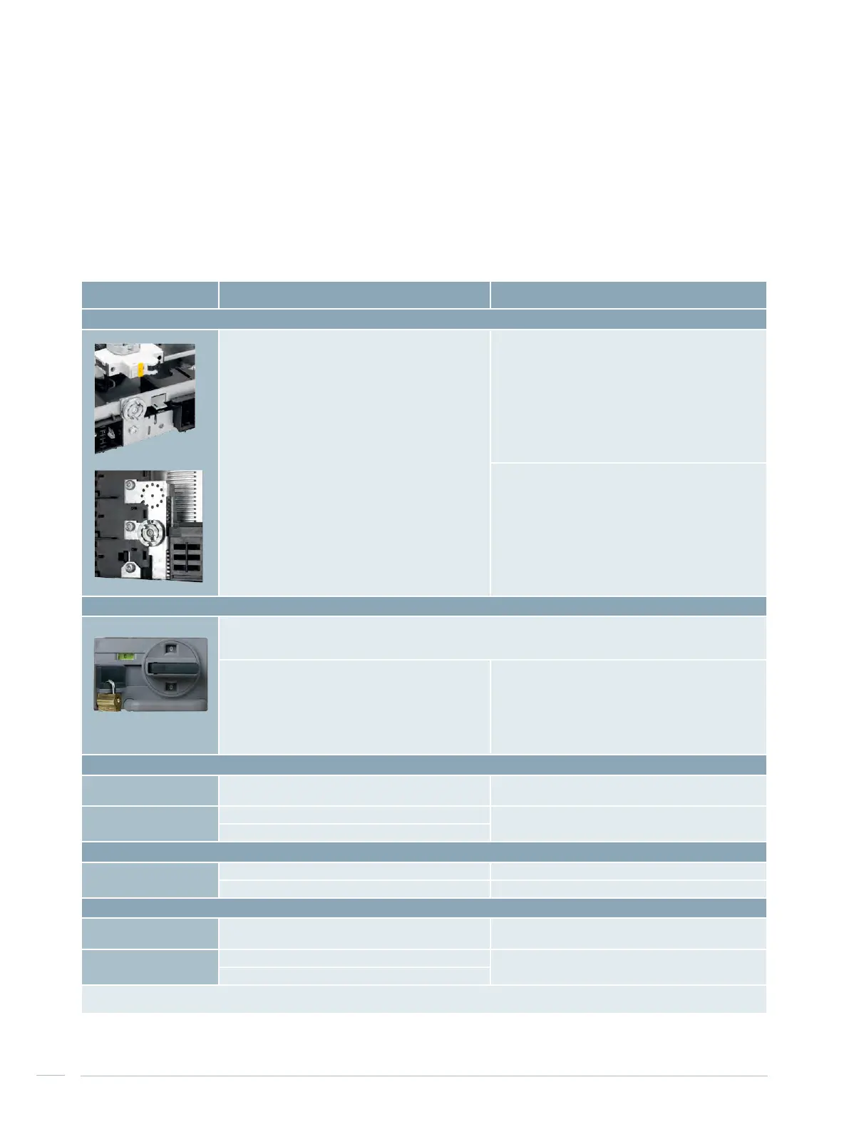
Small withdrawable unit Normal withdrawable unit
Mechanical withdrawable unit coding
96 coding options
(withdrawable unit height 150, 200 mm)
96 coding options (withdrawable unit height 100 mm)
9,216 coding options (withdrawable
unit height > 100 mm)
Locking capability
The withdrawable units can be locked by means of a padlock with a shackle diameter of 6 mm.
The withdrawable unit can then neither be moved to the disconnected, test or connected position
nor be removed from the compartment.
Locking capability of the main switch in the "0" position
is integrated into the control unit:
up to 3 padlocks
with 4.5 mm Ø (shackle)
Locking capability for 3UC7 door coupling rotary drive in
"0" position:
up to 5 padlocks
with 4.5 mm Ø (shackle)
or
up to 3 padlocks
with 8.5 mm Ø (shackle)
Instrument panel
Maximum installation
depth for devices
60 mm 70 mm
Usable front area for installation height 150 mm see Fig. 4/11 see Fig. 4/13
for installation height 200 mm see Fig. 4/12
Withdrawable unit position signal
With optional signalling
switch (-S20)
Feeder available signal Feeder available signal
Test position signal Test position signal
Communication interfaces
PROFIBUS
1)
(up to 12 Mbit/sec)
Via auxiliary contacts of the control plug Via auxiliary contacts of the control plug
PROFINET
2)
Size ¼: One separate RJ45 plug One or two separate RJ45 plug(s)
Size ½: One or two separate RJ45 plug(s)
1)
Apart from that, other protocols based on the EIA-485 (RS485) interface standard such as Modbus RTU can be used
2)
Apart from that, other protocols based on the Industrial Ethernet standard such as Modbus TCP can be used
Tab. 4/13: Characteristics of the withdrawable units in HFD
Characteristics of the withdrawable units in HFD
Tab. 4/13 is subdivided into small and normal withdrawable
units. The installation height has to be observed addition-
ally. The mechanical coding of the compartments and
withdrawable units prevents the exchanging of withdrawa-
ble units of identical size. The control and display devices
for the feeder are installed in the instrument panel.

 Loading...


