57
SIVACON S8 Planning Principles – Cubicles in fixed-mounted design
2
3
4
5
6
7
8
9
10
11
1
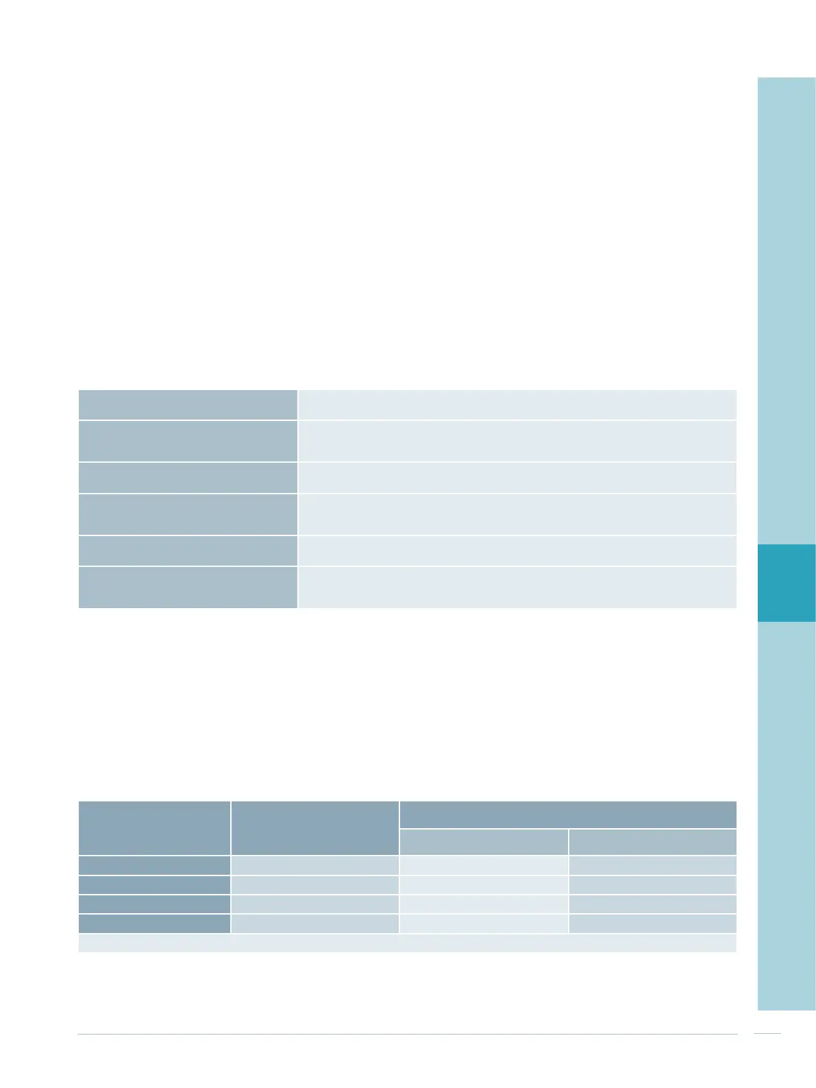
Tab. 6/1: General cubicle characteristics for fixed-mounted in-line design
Application
range
- Incoming feeders up to 630 A
- Outgoing cable feeders up to 630 A
Degrees of protection
- Up to IP31 Ventilated, door with cut-out
- Up to IP43 Ventilated
- IP54 Non-ventilated
Cubicle dimensions - Cubicle height 2,000, 2,200 mm
- Cubicle width (front connection in the cubicle) 600, 800, 1,000 mm
Device compartment
- If cubicle width 600 mm Device compartment width 500 mm
- If cubicle width 800 mm Device compartment width 700 mm
- If cubicle width 1,000 mm Device compartment width 900 mm
Form of internal separation - Form 1b, 2b Door, cubicle high
Design options
- In-line fuse switch-disconnectors 3NJ4 (3-pole)
- With or without current measurement
- Empty slot cover
Tab. 6/2: Rating data of the 3NJ4 cable feeders
General cubicle characteristics
Tab. 6/1 summarizes the general cubicle characteristics.
The switch-disconnectors are fixed-mounted on the hori-
zontal busbar system. Cable connection is effected directly
on the device front. The maximum cable cross sections that
can be connected are stated in the device catalogue. The
cables can be led into the cubicle from top or bottom.
The switch-disconnectors can be equipped with up to three
current transformers to enable feeder-related measure-
ments. In order to implement cubicle-related summation
current measurements, the system provides the option to
install current transformers in the busbar system.
Rating data of the cable feeders
Tab. 6/2 states the space requirements and the respective
rated current dependent on the in-line unit type.
Type
Nominal device
current
Space requirements of the in-
line unit
Rated current
1)
at 35 °C ambient temperature
Non-ventilated Ventilated
3NJ410 160 A
50 mm 117 A 136 A
3NJ412 250 A
100 mm 200 A 220 A
3NJ413 400 A
100 mm 290 A 340 A
3NJ414 630 A
100 mm 380 A 460 A
1)
Rated current with fuse link = nominal device current

 Loading...


