58
SIVACON S8 Planning Principles – Cubicles in fixed-mounted design
Equipment rules for 3NJ4 in-line fuse switch-
disconnectors
Arrangement options for the in-line units in the cubicle:
• From left to right with in-line units decreasing in size
• From right to left with in-line units decreasing in size
The specified rated currents are applicable when the 3NJ4
in-line units are equipped with the largest possible fuse
links. When using smaller links, a corresponding utilization
(in percent) is permissible.
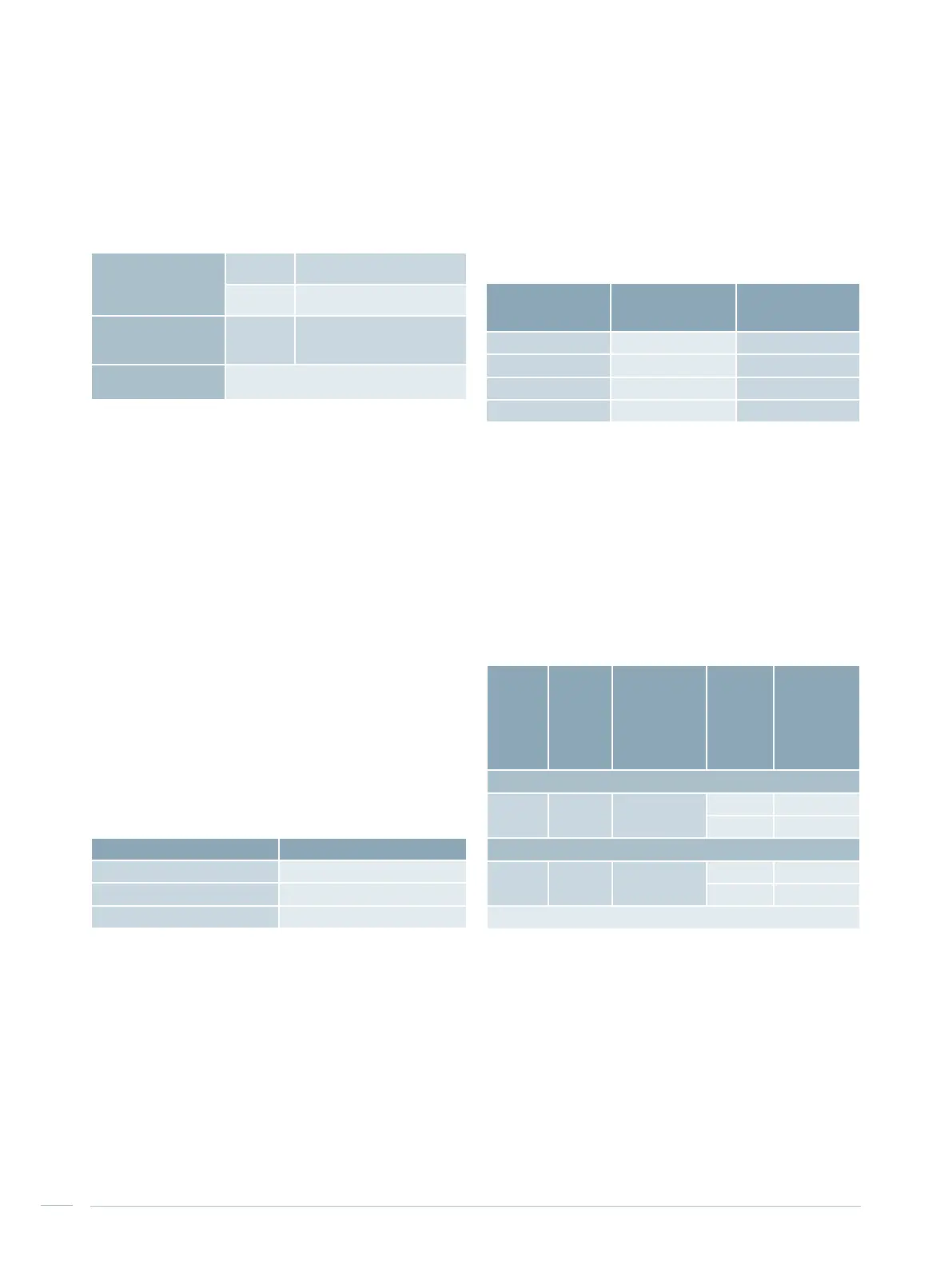
Busbar position Cable connection
Additional built-in
element installed
in the cubicle
Bottom Bottom Top
Top Top Bottom
Bottom Top Not possible
Top Bottom Not possible
Tab. 6/3: Dimensions if additional built-in elements are used
Additional built-in elements
If the busbar and cable connection positions in the cubicle
are identical, one of three possible additional built-in
elements (see Tab. 6/3) can be used. The possible arrange-
ments are listed in Tab. 6/4.
Device holder
Installation
depth
370 mm
Installation
height
625 mm (
cubicle height 2,000 mm)
725 mm (
cubicle height 2,200 mm)
ALPHA 8GK rapid
mounting kit for series-
mounted devices
Height 450 mm (3 rows)
2
nd
row in-line unit
size 00
Data stated in Tab. 6/5 or Tab. 6/6
Tab. 6/4: Mounting location of additional built-in elements
Cubicle width Width of device compartment
600 mm 300 mm
800 mm 500 mm
1,000 mm 700 mm
Tab. 6/5: Device compartment for in-line units in the 2
nd
row
Additional built-in elements for in-line units of size 00 in
2
nd
row
Mounting additional built-in elements for 3NJ4 in-line units
of size 00 is possible for cubicles up to degree of protection
IP31 and operation of the main in-line switch-disconnectors
through the door (door with cutout).
The additional in-line switch-disconnectors are operated
behind the door. This arrangement results in a smaller
width of the device compartment (Tab. 6/5). The rated data
of the cable feeders are stated in Tab. 6/6. The connection
is established directly at the switching device from top or
bottom. Due to the restricted connection compartment,
connections with cable cross sections up to 95 mm² are
possible.
Type
Nominal
device
current
Space
requirements
in-line unit
Max.
number
of
in-line
units
per
cubicle
Rated
current
1)
at 35 °C
ambient
temperature
Installation at the top in the cubicle
3NJ410
160 A 50 mm
10 95 A
14 74 A
Installation at the bottom in the cubicle
3NJ410
160 A 50 mm
10 107 A
14 92 A
1)
Rated current with fuse link = nominal device current
Tab. 6/6: Rating data of the cable feeders for in-line units in the 2
nd
row
Example:
• 3NJ414 in-line unit in a non-ventilated cubicle
(Tab. 6/2: 380 A)
• Equipped with 500 A link
Max. permissible continuous operational current =
= (380 A / 630 A) x 500 A = 300 A

 Loading...


