Scale parameters and functions
8.18 DR18 Control digital outputs
SIWAREX WP251
Manual, 12/2015, A5E37203357A
107
DR18 Control digital outputs
8.18.1
If one or more digital outputs were defined in data record DR 7 for controlling using data
record DR 18 (see Assignment of digital output DQ.0, DQ.1, DQ.2, DQ.3 (Page 91)), this
output can be controlled using data record DR 18. Only outputs that were configured for
controlling using DR 18 (see Overview (Page 86)) are controlled based on the content of
data record DR 18. The set values are not saved in non-volatile memory!
In addition, transitions for the individual weighing steps 0 to 7 can be set in DR 18. With a set
(=TRUE) transition, the respective weighing step is not executed until the corresponding
transition is reset from TRUE to FALSE. The transitions are not saved in non-volatile
memory!
● Check or adapt the desired parameter settings of the digital outputs in data record 7
● Specify the value for digital output DQ.0, DQ.1, DQ.2, DQ.3
● Transfer the data record to the scales
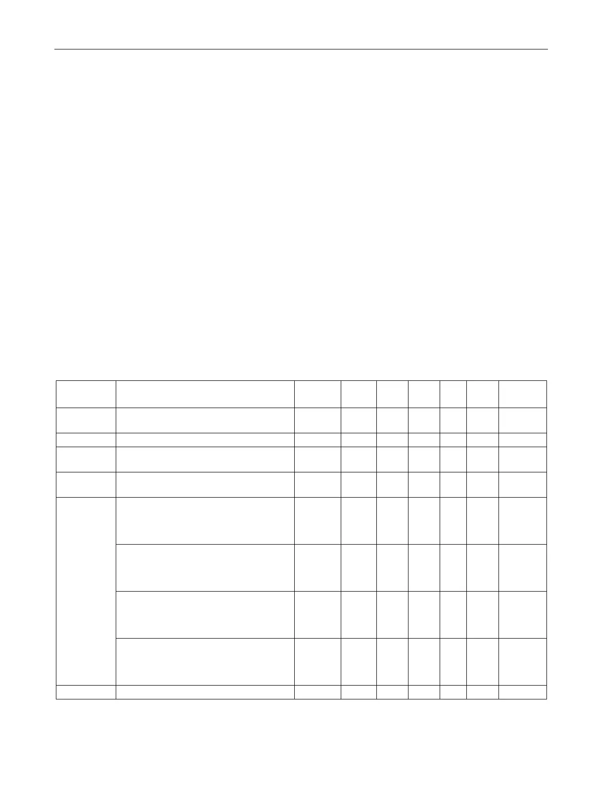
Table 8- 18 Assignment of data record 18
Data record
Contains no. of the data record
USHORT
2
r
18
-
-
1616
Data record length information
Application
Information about which application the DR
belongs to
USHORT
2
r
105
-
-
1618
Version
identifier
Current data record version information
USHORT
2
r
1
1
1619
Specification
for digital
outputs
DQ.0, DQ.1,
DQ.2, DQ.3
(Page 108)
Specification for digital output 0=1 → DQ.0
output active
(only applies if output is assigned function
BIT 0 rw 0 0 1 1620.16
Specification for digital output 1=1 → DQ.1
output active
(only applies if output is assigned function
BIT 0 rw 0 0 1 1620.15
Specification for digital output 2=1 → DQ.2
output active
(only applies if output is assigned function
BIT 0 rw 0 0 1 1620.14
Specification for digital output 3=1 → DQ.3
output active
(only applies if output is assigned function
BIT 0 rw 0 0 1 1620.13