Scale parameters and functions
8.8 DR 7 Process interfaces
SIWAREX WP251
86 Manual, 12/2015, A5E37203357A
DR 7 Process interfaces
8.8.1
Data record DR 7 contains the parameters for defining the properties of the available I/O
modules (digital inputs, digital outputs, analog output, serial ports).
If a port is not used, the default values can be retained.
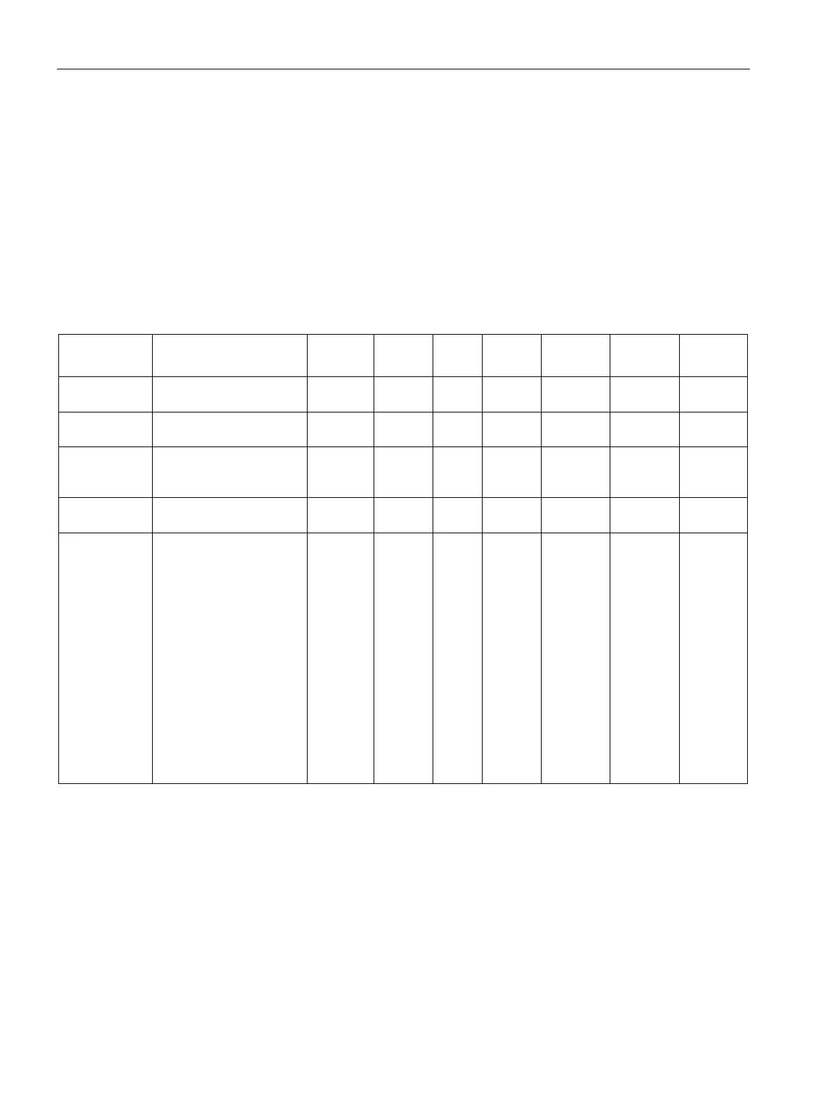
Table 8- 5 Assignment of data record 7
Data record
Contains no. of the data
USHORT
2
r
7
-
-
1300
Length
Data record length infor-
mation
USHORT
2
r
60
-
-
1301
Application
Information about which
application the DR be-
USHORT
2
r
105
-
-
1302
Version identi-
Current data record ver-
USHORT
2
r
1
1
65635
1303
Assignment of
digital input
DI.0, DI.1,
DI.2, DI.3
(Page 90)
Code 0: No command
assigned
1....32759 Command is
triggered at a positive
edge
32760...32767: Transition
for steps 0 to 7 (positive
edge)
32769 … 65527 Com-
mand (command
code+32768) is triggered
at a negative edge
65528...65535: Transition
for steps 0 to 7 (negative
edge)
USHORT 2 rw 0 0 1999 1304