Mobility and Logistics, Traffic Solutions
Sopers Lane, Poole, Dorset, BH17 7ER
Security classification
property name.
Page
61 of 73
Version 008
Status
Released
Last Editor Nathan Fearnhead
Date
16/06/2017
Document Name Configuration Control
Document No.
667/CC/32750/000
Copyright © Mobility 2017. All Rights Reserved. Mobility is a division of Siemens Plc
4.3 Equipment Termination Panel
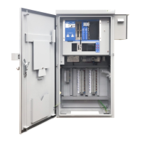
With reference to Figure 62, the Equipment Termination Panel provides the anchor point for
several of the control’s component parts. Stencilled graphics aid the positioning of some
components. Other, large components, have fixed positions. Please refer to the individual
paragraphs below for details on when component positional optimization is required. The
Equipment Termination Panel need not be specified separately as it contained within the
specified Outercase, chosen from Table 6.
4.4 Master Switch Assembly
When configuring a full controller this unit should not be specified separately as it contained
within the Outercase, chosen from Table 6. The Master Switch Assembly is mounted in the
bottom right hand corner of the controller, refer to Figure 62.
With reference to Figure 70 Figure 71, the mains supply voltage
is applied to the main ON/OFF 63A Double Pole Isolator, within the Master Switch Assembly, for
onward supply to the ST750LV Traffic Controller. The live supply wire is taken from the main
ON/OFF 63A Double Pole Isolator and applied to a Master 20A Master fuse.
The output from the 20A Master fuse unit is applied a 5A fuse. Output from the 5A fuse is applied
to 30mA Residual Current Device (RCD) for onwards distribution to the two main outlet sockets.
Space is provided on the Master Switch Assembly to fit an additional 5A fuse; to be utilised as an
auxiliary power supply. Controller mains power Live is taken from the 20A Master fuse and
applied to PL1 on the Phase Drive PCB.
Figure 70 Figure 71
63A Main Double
Pole Isolator
20A fuse
unit
5 A Fuse
30 mA
RCD
Position
for
additional

 Loading...


