SigTEL Compact Installation and Configuration Manual
SigTEL Approved Document No. DAU0000091 Rev 5 Page 12 of 36
Emergency Voice
Communication System
7 Mounting Enclosures
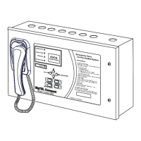
The MCU/LCU is supplied in a steel back-box with a hinged steel lid and several printed circuit boards (PCBs), as
shown below.
The MCU/LCU can be surface, or semi-flush mounted (maximum depth 60 mm including dimples). To expose the
base mounting holes the lid and PCBs must first be removed before installation. Before any of the following is carried
out ensure that the Mains power supply is isolated and the MCU/LCU batteries are removed.
Disconnect the cable from the Power Supply PCB to the Master Exchange PCB and the earth strap from the base
to the lid. Disconnect the earth strap spade connector from the main chassis earth point.
Carefully remove the PCB retaining screw located at the bottom left hand side of the Master Exchange and Power
Supply PCBs.
Push the PCB upwards and then pull forwards over the mounting pillars taking care not to damage any of the
components.
Undo the two screws on the right hand side of the lid using the tool supplied.
Hinge the lid fully to the left. Unplug the earth strap and the two RJ45 plugs on the wiring looms. Carefully remove
the four M4 retaining nuts that secure the hinges.
The MCU/LCU lid and base PCBs should now be removed from site to prevent accidental damage.
Note: All PCBs are static sensitive and anti-static handling precautions MUST be observed when handling them.
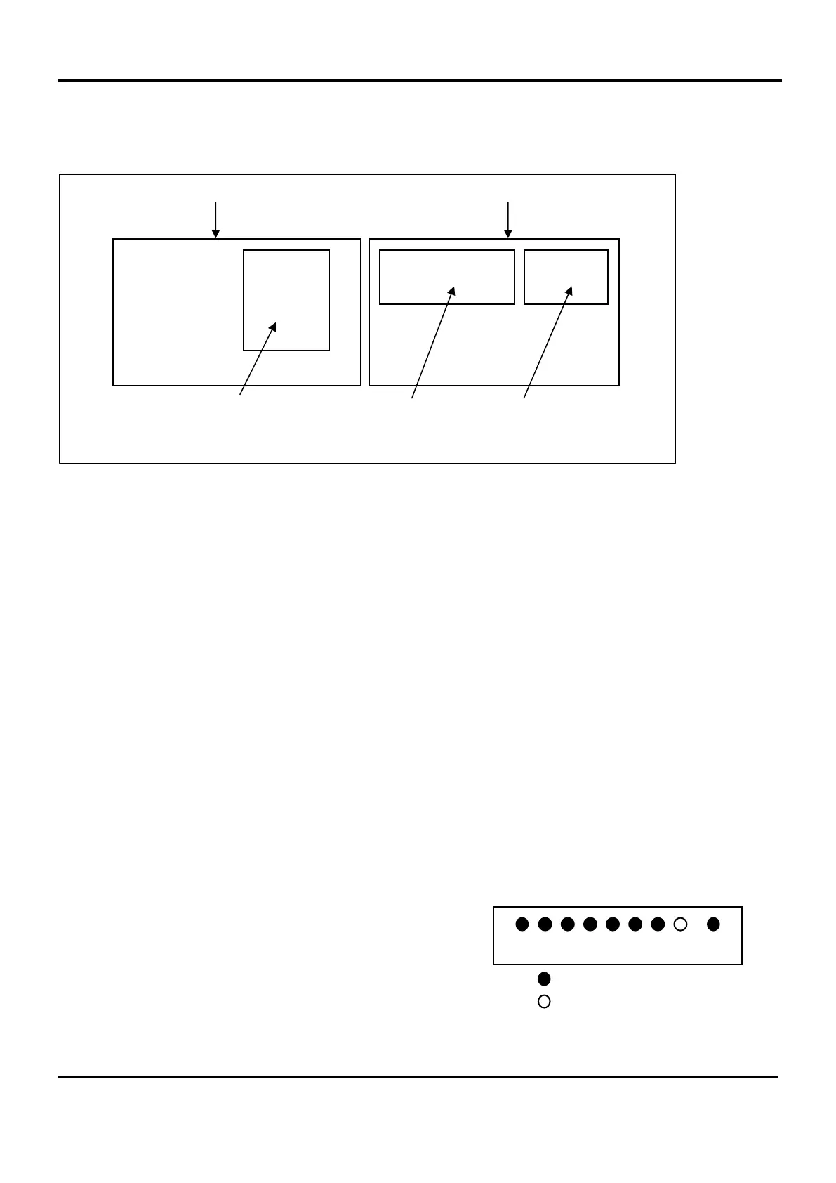
Remove knockouts & cut gland holes
Mains should normally be brought into the base via a knockout
in the bottom right-hand corner. However, if top-entry is
required, it should enter through the knockout on the extreme
right. Cable segregation must be maintained.
If the MCU/LCU is fully populated with extensions then extra
20 mm holes may be cut in the top and rear, as required.
Note: This must be done before re-installation of PCBs to
avoid swarf getting into the electronics.
Control PCB
MCU Hinged Lid MCU Back Box
Master Exchange PCB
MCU
Existing top knockouts
Extra 20 mm hole