SigTEL Compact Installation and Configuration Manual
SigTEL Approved Document No. DAU0000091 Rev 5 Page 22 of 36
Emergency Voice
Communication System
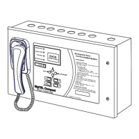
The MCU/LCU external control buttons are located on its keypad. They
are multifunctional dependent on the unit’s current status.
Note: The numbers 1, 2, 3, & 4 are used for entering security PIN codes
using the keypad (by responsible persons only).
When to press this button
Scroll Up
Used to scroll up and down lists (e.g. phone lists) and menus
(e.g. User Options menu).
CALL /
ACCEPT
Make/Accept Calls &
Select Menus
When the MCU’s handset is off-hook press this button to
either make an outgoing call to an extension, or accept an
incoming call from an extension. Also, selects menu options.
END
Ends a Call &
ESC back to previous
display & Lamp test
When the MCU’s handset is off-hook press this button to
disconnect the current caller. When the MCU’s handset is
on-hook press this bu
tton to escape back to a previous
menu. Note: To perform a lamp and buzzer test, press and
Additional functions
& security PIN code entry
Used to access to the ‘User Opts’ menu.
DIRECTORY
& 2
Telephone directory
& security PIN code entry
With the MCU’s handset off-hook, toggles between a full list
of extensions and a list of recent calls from extensions (if
any). Note: The recent calls list is automatically cleared after
a set time period (settable between 6 to 24 hours by a
system engineer). Also, can be manually cleared.
& security PIN code entry
Used to silence the MCU’s internal buzzer.
Note: The controls inside the MCU/LCU are for use by the service company responsible for the EVCS. Under no
circumstances should these internal controls be accessed by Operators.
The Reset and an Engineer Mode buttons are located on the Control PCB inside the front lid. The Engineer Mode button
is used to allow configuration and testing of the system. The Reset button is normally only used to manually initiate a
clean restart to the system, or to reset test calls that have been made from unassigned Type B outstations.
15 Fault Messages
Faults on the EVCS are normally non-latching and will clear if the fault disappears.
The only exception being a watchdog fault which occurs at initial power-up, or after
a system reset and stays latched until manually cleared. Normally this fault clears
when accepted and the MCU/LCU reverts to normal operation.
If the EVCS has been configured previously and any extensions are now missing, or
are incorrectly connected the relevant faults are displayed.
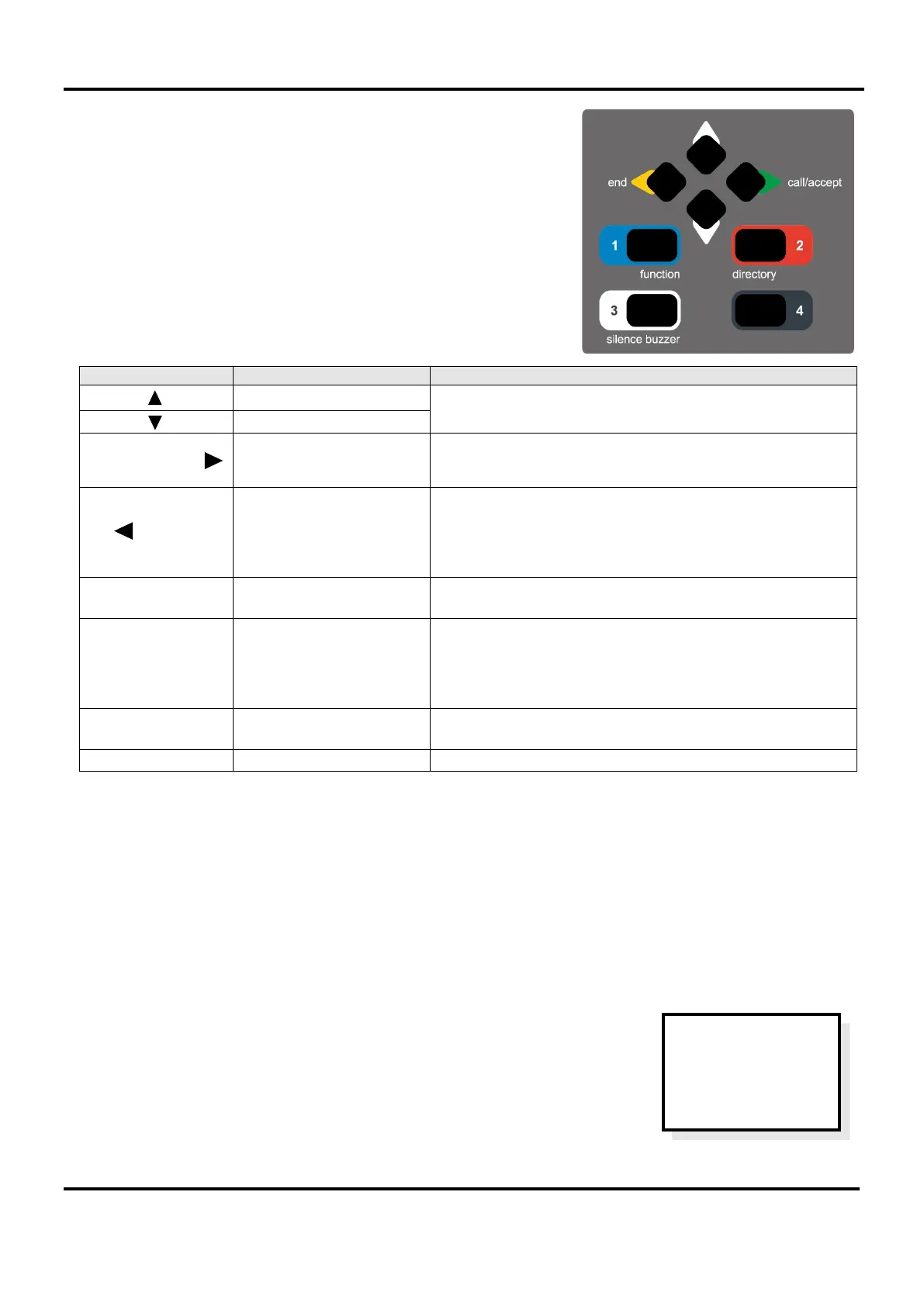
The display (right) shows a typical display but may have a different number of faults.
Press CALL/ACCEPT button to view the fault(s).
EVCS
2 Faults
Press Accept
To View