SigTEL Compact Installation and Configuration Manual
SigTEL Approved Document No. DAU0000091 Rev 5 Page 7 of 36
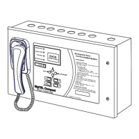
Emergency Voice
Communication System
3.11.1 Key features of the EVCS networked system:
1. Allows the interconnection of up to 14 MCUs or LCUs using 4 x 2-core, 1.5 mm
2
, enhanced fire-rated wiring.
2. Maximum length on the speech wiring loop, or digital linear wiring = 1 km.
3. Each MCU/LCU monitors both the network wiring and each other for faults (open and short circuits).
4. Fault tolerant network that allows the system to continue working in the event of a single cable break in the
speech or digital wiring. Speech audio is transmitted via one wiring loop and digital data via two linear RS485
networks.
5. Each networked MCU can be programmed with the following configuration:
• One MCU is configured as the ‘master’ MCU and has control over the system. The other MCUs act as repeaters but
can take control from the master MCU when a security PIN code is entered, either at the master MCU, or a repeater
MCU. For example, control can be transferred from one control point in a building to another to cater for different
day/night shift patterns.
• The master MCU displays the location of calls and the description of faults on the EVCS. Faults on repeater MCUs
are displayed at the master MCU as remote faults.
• Calls from any outstation, regardless of which MCU they are connected to, are automatically routed to the master
MCU. Repeater MCUs indicate that units are calling the master MCU and can take control of the system by picking
up their handsets and entering a security PIN code.
• Ability to take control from the master MCU at any repeater MCU (by entering a security PIN code). For example,
the nearest MCU to the building entry point. Also, able to give control from the master MCU to any repeater MCU
(by entering a security PIN code).
• Changes made at the master MCU (e.g. security PIN codes, extension names, addition/removal of an outstation or
MCU) are automatically updated on all repeater MCUs.
• The master MCU is automatically dialled to by repeater MCUs when their handsets are picked up (in ‘no-call’ mode).
4 Cables
Generally, cables used between EVCS components, and for the low voltage Mains supply to the system, should be enhanced
fire-resistant [see 26.2e of BS 5839-1]. Please note the following exceptions.
BS 5839-9: section 14 the following recommendations are applicable:
c) Standard fire resisting cables [see 26.2d of BS 5839-1] should be considered to provide sufficient resistance to the effects of
fire with appropriate methods of support and jointing [see 26.2g of BS 5839-1] for:
1) EVC systems for use in disabled refuges but not for fire-fighting or similar purposes by, e.g. the fire and rescue service, in:
• i) sprinklered buildings;
• ii) unsprinklered buildings less than 30 m in height, provided that evacuation takes place in three or fewer phases.
2) Underground sections of cabling at sports and similar venues.
Interconnection Cable Type
Extensions to outstations
2-core, 1.0 mm
2
or 1.5 mm
2
cable is recommended for each extension. Larger
cables will stress the connectors. The maximum cable resistance is 40 ohms, which
is 1 km of 1.0 mm
2
. If this is exceeded audio quality will degrade.
Extensions to DPTA systems (NC951) 2-core cable is required for each extension.
Power supplies
The MCU/LCU requires fixed wiring using 2-core cable and earth/CPC cable (no
less than 0.75 mm
2
and no more than 2.5 mm
2
) fed from an isolating switched fused
spur, fused at 3 amps. A plug and socket MUST NOT be used.
Networked systems
Either MCU to MCU
Or,
MCU to LCU
4 x 2-core, 1.5 mm
2
, up to 1 km in length. This cable connects ECU722 cards
mounted inside the MCU/LCU.
Note: To provide full network reliability only 2-core cable should only be used. This
allows two separate cable paths to be run with each path containing a single speech
and data cable (which should not be mixed in the same cable).
MCU/LCU to ECU722 – Networked
systems
Connects the MCU/LCU to the ECU722 comms card using one Cat 5 patch cable
(supplied with ECU722).