SigTEL Compact Installation and Configuration Manual
SigTEL Approved Document No. DAU0000091 Rev 5 Page 32 of 36
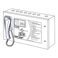
Emergency Voice
Communication System
19 Component Specifications
Note: This specification applies to MCUs (ECU-16, ECU-8, ECU-4) & LCU (ECU-8NT) unless stated.
Power Supply and Batteries
2 x 12 V, 7 Ah (Part No. BC286/2)
Mains supply/battery charger monitored for failure
Batteries monitored for disconnection and failure
Quiescent current when operating on batteries only
MCU/LCU only with Mains fault buzzer silenced
MCU/LCU only with Mains fault buzzer sounding
Quiescent current per Type A outstation
Quiescent current per Type B outstation
Off-hook current per Type A outstation
Off-hook current per Type B outstation
* 16 Type B outstations fitted; one connected, 15 calling in.
OP1, OP2, OP3 open collector outputs
Microphone frequency response
Earpiece frequency response
250 Hz to 4 kHz +/- 3 dB
Loudspeaker frequency response
Maximum number of extensions per MCU/LCU
16 (ECU-16), 8 (ECU-8), 4 (ECU-4) / 8 (ECU-8NT)
Number of outstations or DPTA per extension
Extensions monitored for open-circuit and short-circuit
1.5K, 0.25 W, 10% (supplied in accessory pack)
Extensions to outstations
2-core, 1.0 mm
2
or 1.5 mm
2
, enhanced fire-rated cable, up to 1 km per
extension (maximum cable resistance is 40 ohms)
Extensions to DPTA systems (NC951)
2-core cable is required for each extension
Power supplies
Fixed wiring using 3-core fire-rated cable (no less than 0.75 mm
2
and no
more than 2.5 mm
2
) fed from an isolating switched fused spur, fused at 3 A
MCU to MCU/LCU – networked system
4 x 2-core, 1.5 mm
2
enhanced fire-rated cable, up to 1 km in length
MCU/LCU to ECU722 – networked
system
One Cat 5 patch cable (supplied with ECU722)
Liquid Crystal Display (LCD)
128 x 64 pixel graphic LCD unit, two-colour backlight
Controls (pushbuttons)
, Function, Directory,
Silence Buzzer, Four numbered buttons (1, 2, 3 & 4)
Indicators (LEDs)
Disablement (Amber), System Fault (Amber), PSU Fault (Amber),
General Fault (Amber), Power (Green)
Internal controls (pushbuttons)
Label background Pantone 429C. Lid and base RAL7035 (Grey texture)
EVC302F/GF and EVC302S/GS
Fascia stainless steel (EVC302F and EVC302S), Fascia mild steel green
(EVC302GF and EVC302GS). Base RAL 9005 (Jet Black)