SigTEL Compact Installation and Configuration Manual
SigTEL Approved Document No. DAU0000091 Rev 5 Page 23 of 36
Emergency Voice
Communication System
Each fault display has two lines. The format depends on whether the fault relates to an extension or not.
Format 1: Extension faults
Format 2: Non-extension faults
Line 1 - Extension name
Line 2 - Fault description
Line 1 - Fault description, e.g. Mains fail
Line 2 - Blank
Clearing faults
Most faults can be cleared in turn (e.g. watchdog fault), by pressing the CALL/ACCEPT button. Each fault that is no
longer present will clear and the next fault will be presented.
You can also press ▲ and ▼ to navigate through the faults and select which ones to clear.
Remaining faults
All outstation faults should be cleared before configuration. Some faults, such as Mains fail when setting up on
batteries, may not clear and will stay on the display. Some faults may require investigation, or assistance from the
service company responsible for the EVCS. If required, contact them directly for assistance quoting the exact nature
of the fault which is shown on the display.
16 Powering Up and Testing
Setup using batteries
These instructions assume that the system is being set up and
configured on batteries only. If it is configured on Mains only, or
Mains and batteries, the fault displays will change accordingly.
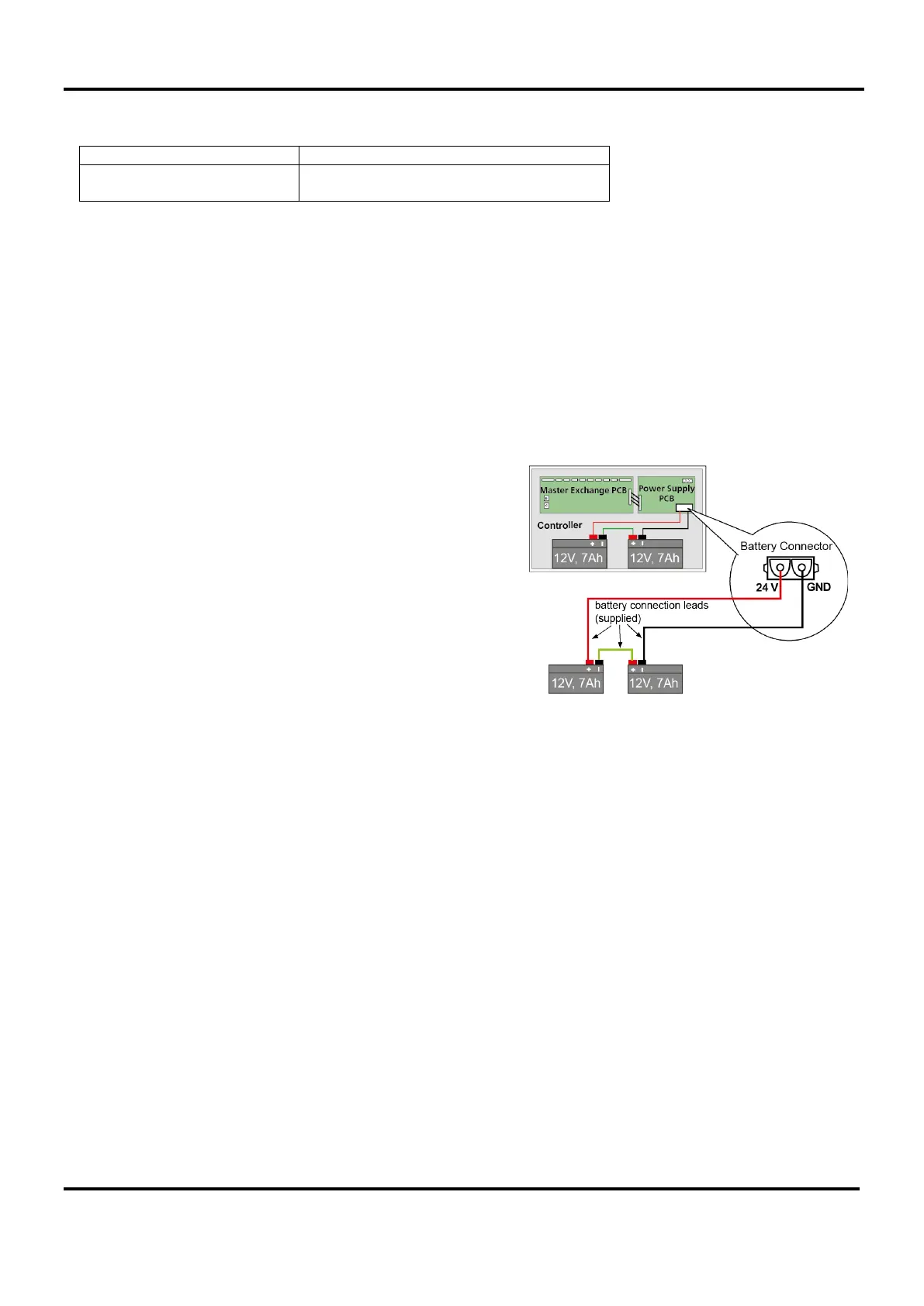
Two 12 volt, 7 Ah VRLA batteries (BC286/2) should be used with
each MCU/LCU. These should be connected in series using the
link supplied with each unit. The terminal voltage of the batteries
must be at least 22 V.
Do not leave batteries attached for long time periods whilst the
Mains is not connected as they will become fully discharged and
will have to be replaced.
Setup using Mains
Fit a 3 amp fuse into the switched fused spur and turn the power on.
Turn the power on
As soon as the MCU receives power the handsets may ring for a moment and the MCU will sound an intermittent
fault buzzer due, at least, to a Watchdog Fault. The Power LED, System Fault LED, PSU Fault and General Fault
LED will be lit.
Cancel the fault buzzer by pressing SILENCE BUZZER button.
Check the outstations are working
Go to each outstation in turn.
At Type A outstations the LED on the handset cradle will be lit. Pick up the MCU’s handset and speak. If you hear
yourself in the earpiece then it is correctly connected.
At Type B outstations press the ‘Push to Call or Answer’ button and the red LED will light. This cannot be cancelled
so when you have finished checking them all, press the Reset button inside the MCU/LCU lid.
When all outstations are working, clear the fault display to make sure that there are no other problems and then use
Auto Learn option to begin the system configuration (see section 17). If faults are present, handsets are off-hook, or
call/answer buttons have been pressed, then the Auto Learn option will abort.
Check the toilet alarms are working
Go to each toilet alarm system in turn. Initiate an alarm from a call unit on each system and confirm the call is
displayed at the MCU/LCU. Ensure all toilet alarms are cleared and reset.
Note: Toilet alarms can only be reset at the alarm point and cannot be reset at the MCU/LCU.