SigTEL Compact Installation and Configuration Manual
SigTEL Approved Document No. DAU0000091 Rev 5 Page 20 of 36
Emergency Voice
Communication System
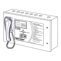
1. I/P A (Disable controls) – Disables Type A and Type B outstations.
2. I/P B (Disable controls) – Disables input signals from the DPTA.
In order to prevent unauthorized use of the system it is possible to disable the controls until an external trigger
is received, e.g. from a fire alarm control panel. I/P A & B are open-circuit, fail-safe system disablement inputs.
Closing these inputs (shorting the connections) disables the system so that the system can then be enabled
by opening the connections. No system configuration is required to use this facility and if they are left
unconnected it will operate normally.
Note: For a network system, only one MCU/LCU requires I/P A or I/P B wiring to the disablement source.
3. I/P C - Not currently used.
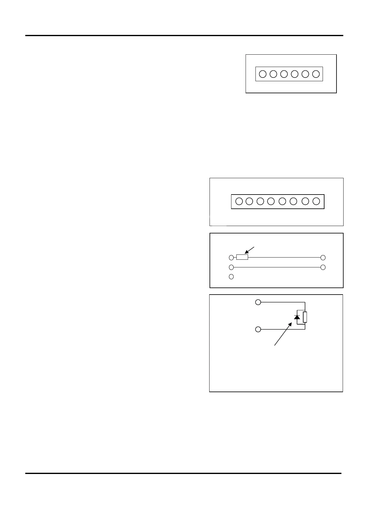
1. Fault output - The terminals marked N/O, C and N/C
(see right) provide fail-safe fault outputs that can be
connected to a fire alarm panel or other monitoring
equipment.
The end-of-line device supplied with the input unit should
be connected at the MCU/LCU in order to monitor the
wiring (see example right). When a fault occurs the relay
disconnects the end-of-line device from the fire alarm
panel.
Note: For a network system, all MCU/LCU fault output
relays will be activated.
2. +24 V - Used to supply the output’s auxiliary equipment,
e.g. relays, etc.
3. OP1 output – activates whenever the master MCU is
ringing. Its main purpose is to provide an indication
(possibly remote), e.g. to a strobe, beacon, etc. when
someone is seeking assistance.
4. OP2 output – provides the equivalent function as OP1
output (above) for active toilet alarms.
5. OP3 output – closes when the handset is off hook and
remains active for 2 minutes after the handset is put
down. This function may be used to turn off noisy
equipment in the locality of the controller that may affect
communication.
N/C
C
I/P +
End-of-line device
N/O
Example use of Fault O/P
I/P -
N/O C N/C 0V +24V OP3 OP2 OP1
I/P A I/P B I/P C
+ - + - + -
OP1, 2 or 3
+ 24 V
Relay
coil
Example use of OP1, OP2, OP3
To protect the output stage, only 24V polarised
relays with back EMF diodes should be used