SigTEL Compact Installation and Configuration Manual
SigTEL Approved Document No. DAU0000091 Rev 5 Page 27 of 36
Emergency Voice
Communication System
Adding or re placing MCU/LCU, outstations or DPTA after commissioning
Note: Compatibility issues may arise if adding/replacing a panel with the latest firmware onto a networked system
with earlier firmware. Some features of the new firmware may be disabled/unavailable to ensure smooth compatibility
with the panels with earlier firmware. If the latest features are required, the other panels on the network must be
replaced.
Firstly, make the necessary electrical or mechanical changes and all faults are cleared on the system.
To add an MCU/LCU (network system): Open the lid of the MCU/LCU and press the Engineer Mode button.
Select the ‘Config’ menu, then ‘System Cfg’ menu and then select ‘Unit Count’ option. Press ▼ or ▲ to set the
number of MCU/LCU on the network including the master MCU (2 to 14) and press CALL/ACCEPT button. The
master MCU then requests repeater MCU/LCU to join it on the network. If an MCU/LCU is joining the network,
go to that unit and press CALL/ACCEPT button. The system will automatically perform an Auto Learn, search
the network for all MCU/LCU and display the system configuration at the master MCU.
To replace a faulty MCU/LCU (network system): Make sure that the faulty panel you are replacing is not the
designated ‘Master’. At the master MCU, open the lid and press the Engineer Mode button. Select the ‘Config’
menu, then ‘System Cfg’ menu and then select ‘Unit Count’ option. Press ▼ or ▲ to set the number of MCU/LCU
on the network including the master MCU (2 to 14) and press CALL/ACCEPT button. The master MCU then
requests repeater MCU/LCU to join it on the network. If an MCU/LCU is joining the network, go to that unit and
press CALL/ACCEPT button. The system will automatically perform an Auto Learn, search the network for all
MCU/LCU and display the system configuration at the master MCU.
To add/remove an outstation or DPTA (non-network and network system): Open the lid of the master MCU
and press the Engineer Mode button. The ‘Eng. Opts’ menu is displayed. Select the ‘Config’ menu, then ‘System
Cfg’ menu, and then select ‘Auto Learn’ option. The system will automatically perform an Auto Learn and search
for connected extensions. The system configuration is displayed at the MCU (or master MCU on a networked
system).
On a networked system, the controller (MCU/LCU) extensions are allocated the following default names:
Controller 1: Extension 1 to Extension 16
Controller 6: Extension 81 to Extension 96
Controller 11: Extension 161 to Extension 176
Controller 2: Extension 17 to Extension 32
Controller 7: Extension 97 to Extension 112
Controller 12: Extension 177 to Extension 192
Controller 3: Extension 33 to Extension 48 Controller 8: Extension 113 to Extension 128 Controller 13: Extension 193 to Extension 208
Controller 4: Extension 49 to Extension 64
Controller 9: Extension 129 to Extension 144
Controller 14: Extension 209 to Extension 224
Controller 5: Extension 65 to Extension 80
Controller 10: Extension 145 to Extension 160
Open the lid of the MCU/LCU (or, in the case of a networked system, the master MCU) and press the Engineer
Mode button. The ‘Eng. Opts’ menu is displayed.
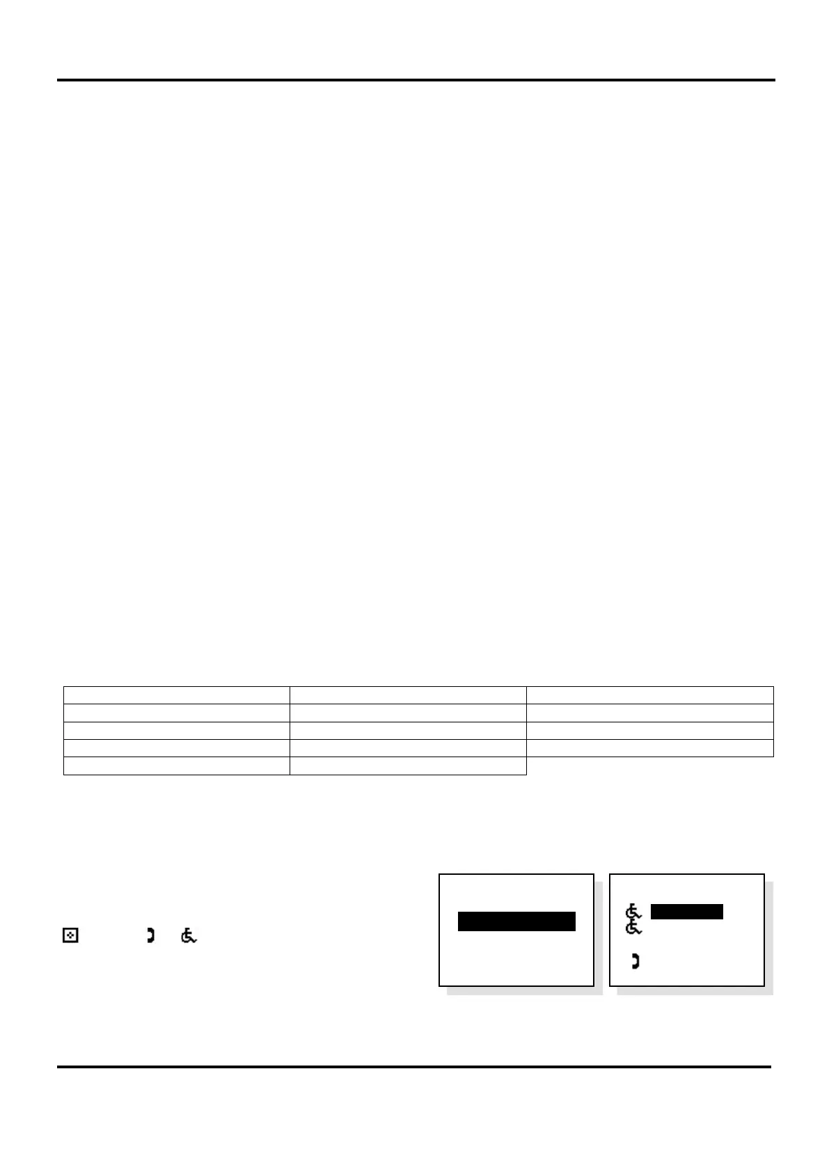
Select ‘Edit Phonebook’ option, see right.
A list of all system devices will be displayed:
or □ or or or
w
c
symbols denote whether they
are an MCU, LCU, Type A outstation, Type B outstation, or
DPTA, see far right.
To edit the extension names, see manual naming section 17.5.2.
Name List
> Extension 1
Extension 2
w
c
Extension 3
Extension 4
Eng. Opts
> Edit Phonebook
Config
About...