SigTEL Compact Installation and Configuration Manual
SigTEL Approved Document No. DAU0000091 Rev 5 Page 26 of 36
Emergency Voice
Communication System
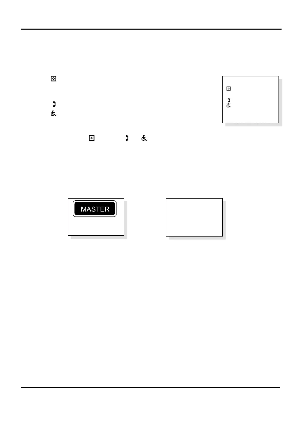
6. After all repeater MCU/LCU have joined the network, the system will automatically perform an Auto Learn
and detect the attached extensions. The Auto Learn system configuration is displayed at the master MCU,
see example below right.
Note: If a fault message is displayed at the master MCU an Auto Learn may not have been performed. Press
END button to exit the fault menu and start the Auto Learn process.
The symbol denotes the number of MCU (ECU-16, ECU-8 or ECU-4).
Note: This is a maximum of 14 units for a networked system.
The
□ symbol denotes the number of LCU (ECU-8NT).
The symbol denotes the number of Type A (fire telephone) outstations.
The symbol denotes the number of Type B (disabled refuge) outstations.
The
w
c
symbol denotes the number of DPTA on the system.
Check the number of and
□ and and and
w
c
match the number of network devices.
Note: If at this stage there is a mismatch between the expected and the displayed number of network devices,
press the CALL/ACCEPT button again at the master MCU whilst the Auto Learn system configuration is
displayed. This will cause the system to perform another learn of the network devices.
7. Press END button multiple times to exit to the system healthy display.
The master MCU and repeater MCU/LCU will display their network status. See examples below.
The system is now configured and can be used.
Note: Extension names can be added/edited at this point (see naming extensions – sections 17.5).
System Healthy
Master is
Controller 1
System Healthy
Auto Learn
: 3
□: 1
: 3
: 13
w
c:
4
System Updated