SigTEL Compact Installation and Configuration Manual
SigTEL Approved Document No. DAU0000091 Rev 5 Page 18 of 36
Emergency Voice
Communication System
11 Fitting Outstations & DPTA Interface
See section 4.
See section 6.1.
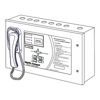
Fitting type A outstation (EVC301RPO/EVC301RLK)
Open the case and unscrew the fixing screw at the bottom of the unit and
remove the internal cover (see far right). This reveals the terminals and
earth stud. Fix to the wall, remove the knockout above the terminals and
fit a suitable cable gland. Connect the wires, as shown right.
For further details refer to Type A outstation instructions (DCM0003819).
Fitting type B outstation (EVC302S/GS and EVC302F/GF)
Type B outstations are supplied complete with a back box that should be fitted to the wall using suitable fasteners.
The back box has 20 mm knockouts at the top and bottom. Gland the cable correctly and connect a sleeved earth
wire to the earth stud.
Connect the line to the LINE IN + and LINE IN – terminals.
When installation is complete, secure the lid using the four machine screws. These have a secure pin-hex design
that requires a special Allen key (supplied).
For further details refer to Type B outstation instructions (DAU0302000).
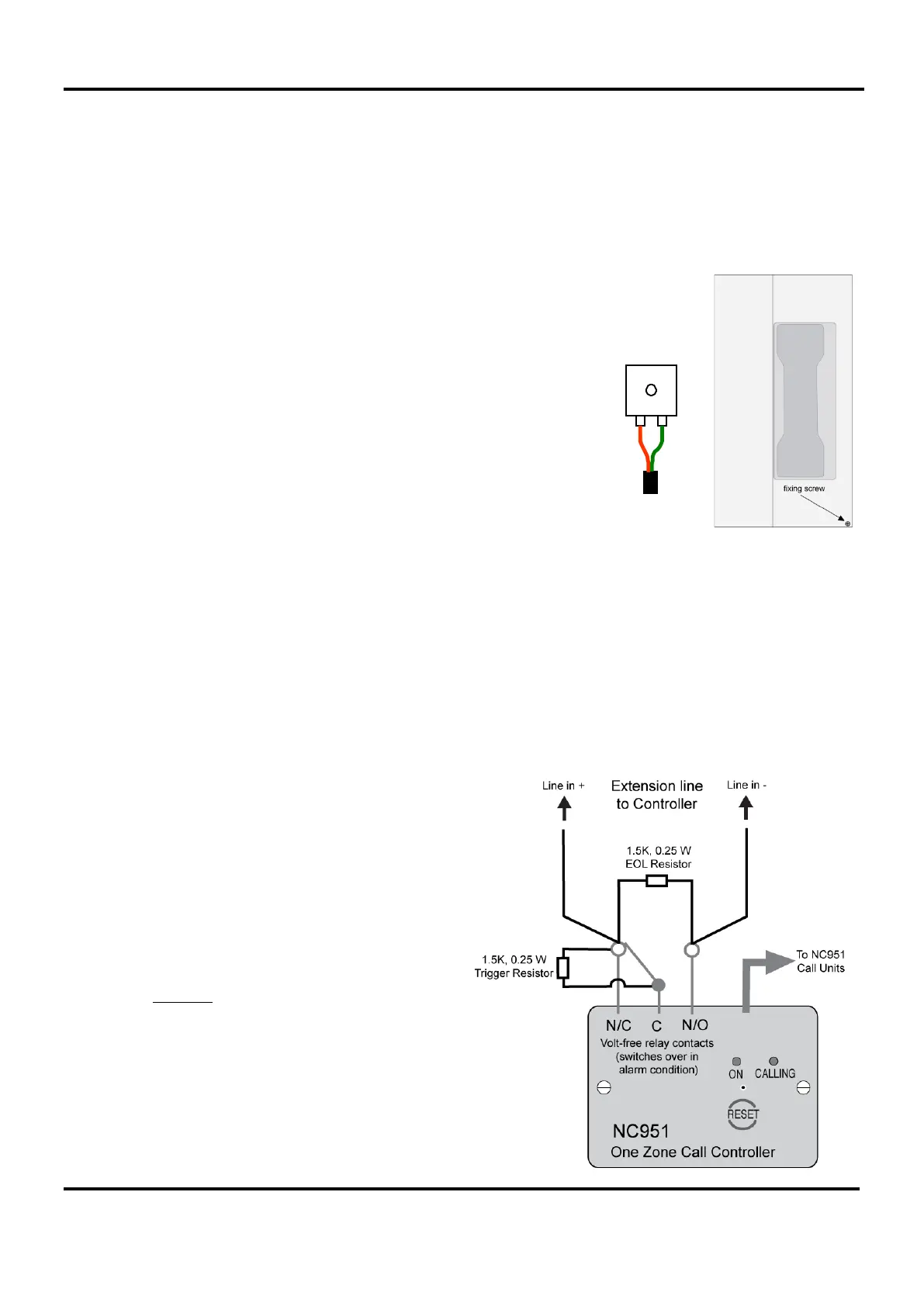
Wiring to a disabled persons toilet alarm (DPTA)
To install the DPTA system, refer to the documentation supplied with the DPTA (Part No. NC951).
To interface the DPTA system to the EVCS, see wiring
diagram right. The NC951 has an on-board volt-free
relay.
Two 1.5k, 0.25 W, 10% resistors are supplied with the
NC951; the EOL resistor identifies the extension as a
DPTA and the trigger resistor when switched in, asserts
an active alarm on the EVCS.
Please note the stainless steel DPTA (Part No.
NC951/SS) does not have an on-board volt-free relay.
An additional 12 volt relay (Part No. NC883D) is
required to interface to the EVCS. Contact your supplier
for purchase information.