SigTEL Compact Installation and Configuration Manual
SigTEL Approved Document No. DAU0000091 Rev 5 Page 15 of 36
Emergency Voice
Communication System
8 Installing the ECU722 Network Comms Card (Optional)
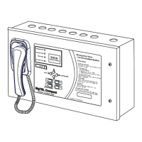
The MCU/LCU has a Master Exchange PCB and Power Supply PCB mounted in its base unit and a lid-mounted Control
PCB. The ECU722 card has to be mounted on top of the Master Exchange PCB. Before carrying out the steps below,
ensure that Mains power is isolated and the MCU/LCU batteries are disconnected.
Note: All PCBs are static-sensitive and therefore anti-static handling precautions MUST be observed when handling
them.
To install an ECU722 card follow the steps below:
1. Open the MCU/LCU lid by removing the two retaining lid screws (using an Allen key).
2. Disconnect the 10-way wiring loom between the Master Exchange PCB and the Power Supply PCB. Ensure
the loom remains connected to the Power Supply PCB to prevent it being misplaced.
3. Unplug the RJ45 connectors from terminals B&C
on the Master Exchange PCB. Ensure these
cables remain connected to the Control PCB to
prevent them being misplaced. Care should be
taken when detaching these connectors to
depress the locking tabs to prevent damage.
4. Unfasten the one retaining screw, located bottom
left side on the Master Exchange PCB, using a
crosshead screwdriver. Carefully slide the Master
Exchange PCB up and over its mounting pillars,
taking care not to damage any components.
5. Take the ECU722 card and carefully line up its
four holes with the holes in the Master Exchange
PCB, see right.
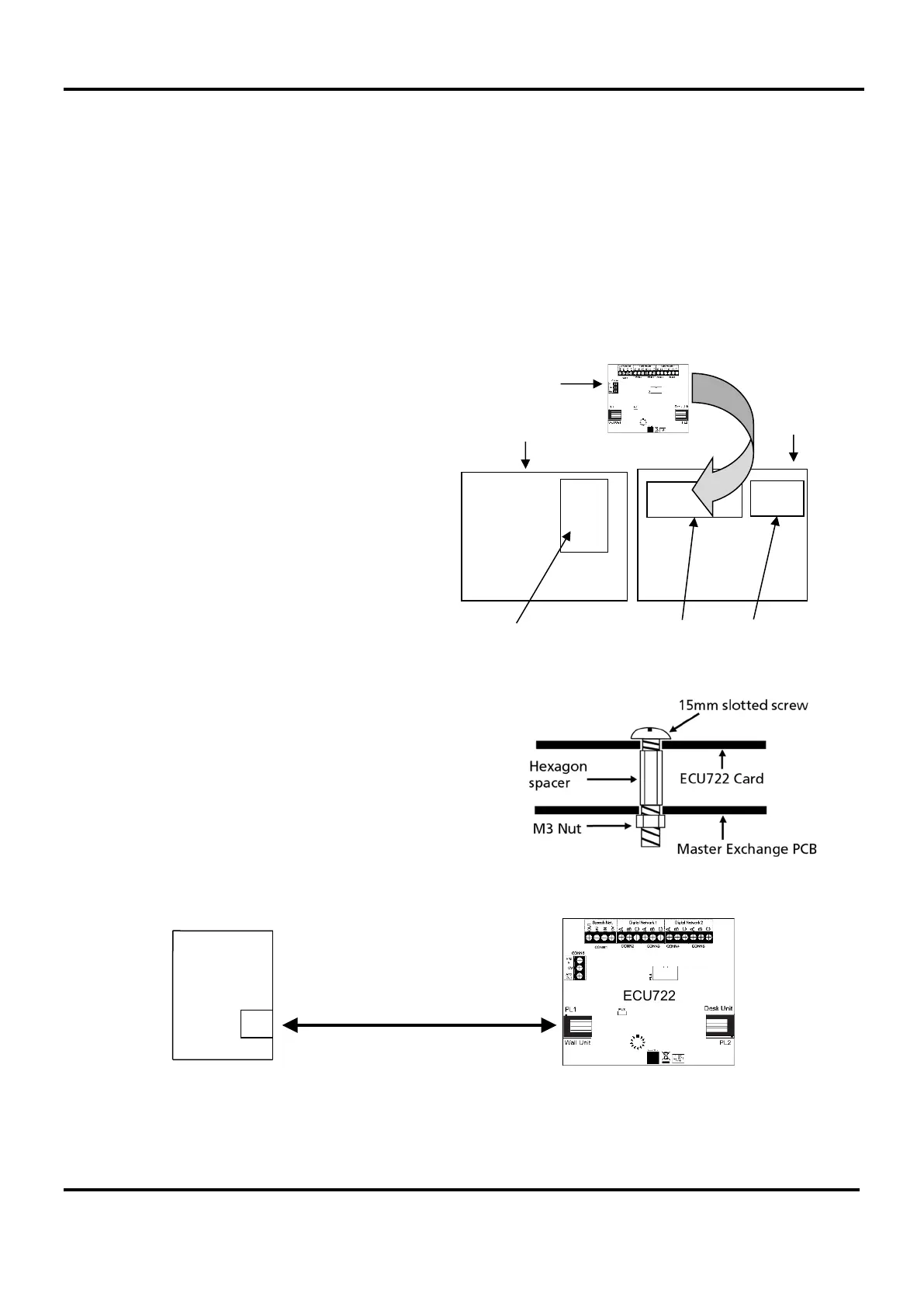
6. Insert four M3 x 15 mm slotted screws and hex
spacers (supplied) through the front holes in both
the ECU722 card and Master Exchange PCB so
they protrude through the back of the PCB. Next,
secure the ECU722 card and PCB together using
four M3 nuts (supplied), see right.
7. Refit the Master Exchange PCB (and mounted
ECU722 card) back into the base unit. Ensure the
retaining screw on the Master Exchange PCB is
firmly fastened down. Reconnect the RJ45 cables
and 10-way wiring loom.
8. Connect a Cat 5 cable (supplied) from terminal G
on the Control PCB to PL1 on the ECU722 card.
See below.
9. When all connections have been correctly made, re-connect power to the MCU/LCU.
ECU722
G
Control
PCB
Control PCB
Power Supply PCB
Fitting the ECU722 card
MCU Lid
Master Exchange PCB
MCU
Back Box
ECU722