DL100 Series Universal Low-Power Inverter
30 Detailed Description of Functions
LED ten digits: operation command mode selection
0:Two-line mode 1 (default mode)
In the two-wire mode, one input terminal X1~X4 must be selected as the
forward control terminal FWD, and the other input terminal X1~X4 is the
reverse control terminal REV (refer to the description of parameters [F3.01]
~[F3.04])
1:Two-line mode 2
2:Three-line mode
For the three-wire control mode, one input terminal (X1~X4) must be selected
as the forward control terminal FWD, one input terminal (X1~X4) is the
three-wire operation control terminal SW1, and one input terminal (X1~X4) is the
reverse control terminal REV ( Refer to the description of parameters
[F3.01]~[F3.04]), select any three of the input terminals X1-X4 by parameters
[F3.01]~[F3.04].
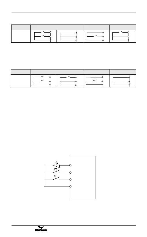
The switch function description is as follows:
1. SW1(Three-wire operation control terminal) —— Inverter stop trigger
switch
2. SW2(FWD) —— Forward trigger switch
3. SW3(REV) —— Reverse trigger switch
F
igure 6-2 Wiring diagram of three-wire control mode