DL100 Series Universal Low-Power Inverter
Detailed Description of Functions 31
Hundreds of LEDs: reserved
Thousands of LEDs: self-start after power-on
0:Power-on self-start prohibition
1:Power-on self-start allowed
LED ones:Reverse running direction
0:Invalid
1:Inverted direction is valid
LED Hundreds:Reversal prevention
0:Invalid orientation lock
1:Reversal prevention
2:Forward rotation prevention
This parameter determines the switching frequency of the internal power
module of the inverter.
The carrier frequency mainly affects audio noise and thermal effects during
operation. When silent operation is required, the carrier frequency can be slightly
increased, but the maximum load that the inverter can carry will decrease, and the
interference range of the inverter to the outside world will increase. For long
motor cables, the leakage current between the motor cables and between the cable
and the ground may also increase. When the ambient temperature is high, the
motor load is heavy, or the inverter fails due to the above reasons, the carrier
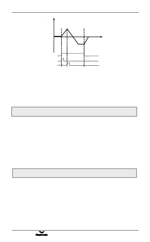
Figure 6-3 Frequency output diagram of three-wire control mode
F0.08 Carrier frequency Setting range
:
2.0 ~ 8.0 KHz
F0.07 Running direction setting Setting range: 0000 ~ 0011