Instruction Manual
39
E04052
The first link in the IS12 system is the power cable, which
should be connected to the boat’s 12v DC supply via a 3 Amp
breaker or fuse as follows -
Red wire - 12v DC
Black wire - 0v
NOTE Only one power cable is required in an IS12 system, but
power must be supplied via an IS12 power cable (with a red
connector end), or the system will not function.
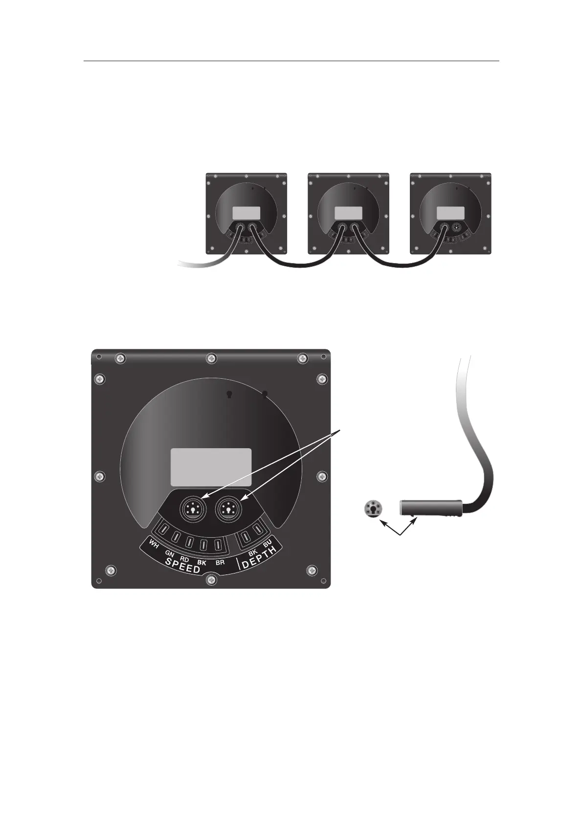
Fig 4.15 - IS12 “Daisychain” Cable System
Fig 4.16 - Rear Connections
Flattened edge
Network Bus Ports
4.3 Electrical Installation
IS12 instruments are ‘daisy chained’ together, with each instru-
ment linking to the previous one by a single cable carrying
power and data (Fig 4.15). The cable plugs into either of the
two circular network ports on the rear of the instrument.
The cable connectors are keyed so that they will always be cor-
rectly oriented when inserting the cable into the instrument -
the flattened edge of the connector should be facing down
when inserting (Fig 4.16) -