3.2. Pump elements
Piston pump units with reservoir possess two
lubricant outlets that can be equipped with a pump
element. Unused pump outlets must be closed using
a screw plug.
The pump elements meter the lubricant then feed it
into the main lubricant line of the centralized
lubrication system.
Model designs with progressive distributors (3- to
9-port) mounted on the pump housing feed the
lubricant directly into the progressive distributor.
The lubricant is then transported from the feeder's
outlets directly to the lubrication points.
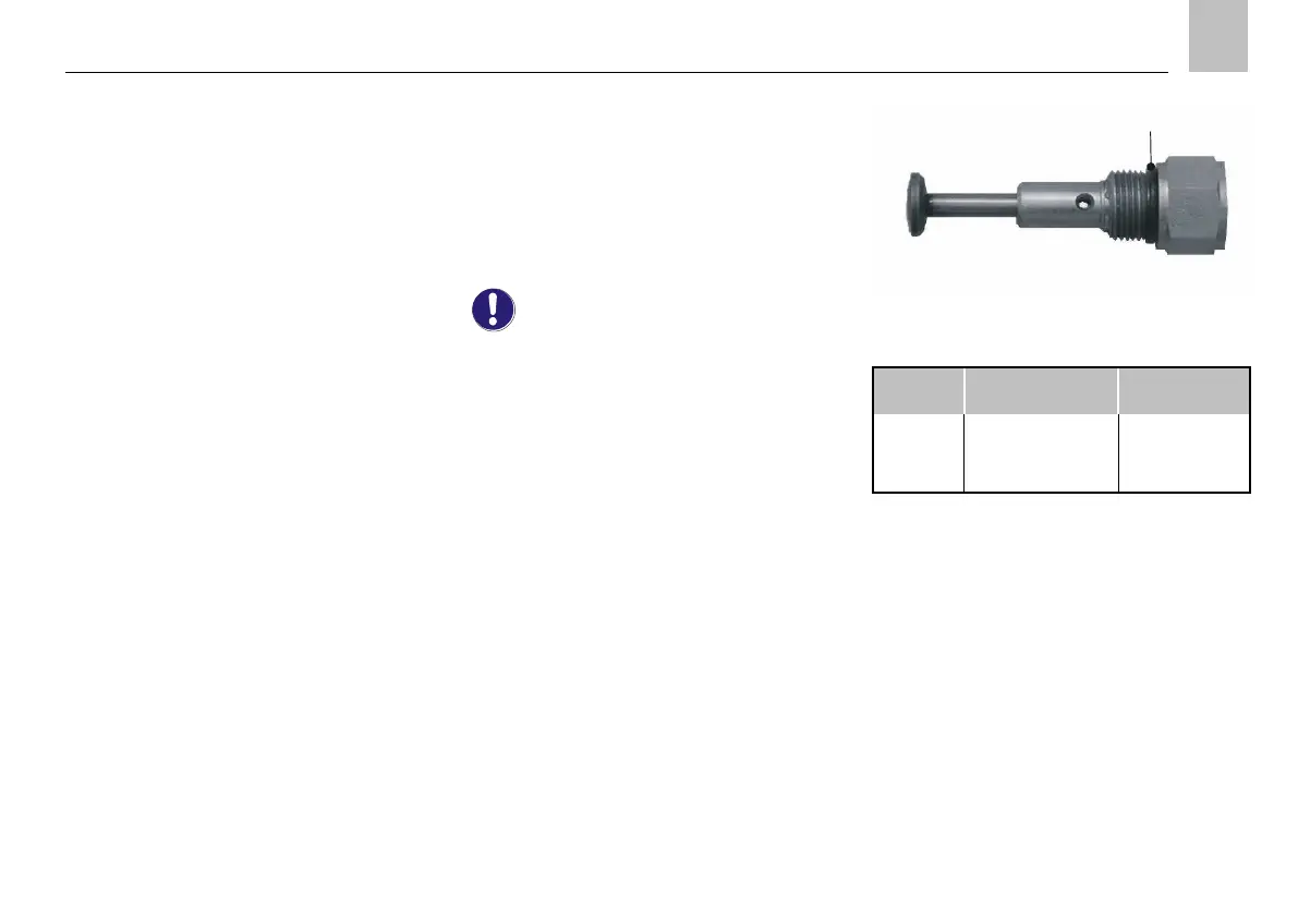
The pump elements are designed for different
delivery rates depending on the lubrication task. The
different designs are indicated by grooves on the
wrench flat ( Table5).
For additional details about the pump elements, see
the associated documentation.
If no documentation is available, you can
request the documentation directly from
SKF Lubrication Systems Germany GmbH .
 Loading...