4. Assembly instructions Page 19
4.4.2. KFA1, KFA1-W (commercial vehicles)
Supply voltage 12/24 V DC
For voltage specifications, see the
rating plate of the piston pump unit and
Table 8.
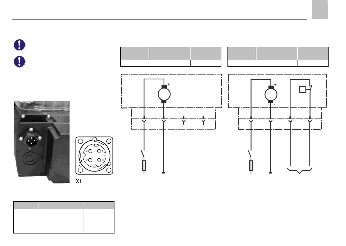
The electrical connection of the piston pump units is
established via a 4-pin circular connector according
to DIN 72585-A1-4.1-Ag/K1.
Fig.5. Circular connector
Table 9. X1 4-pin circular connector
KFA1 without fill level monitoring
Table 10. Cable set
Length of corrugated
hose
KFA1
M
X1 1 2
3
4
5) 5)
RD-BK
BN
1)
F 3 A
15 31
Fig.6. Electrical connection of KFA1
1) External control unit;
relay contact "Pump ON"
5) PIN without internal connection
F Fuse
See Table9 for color coding.
KFA1-W with fill level monitoring
Table 11. Cable set
Length of corrugated
hose
KFA1-W
M
X1 1 2
3
4
RD-BK
BN
BK
PK
1)
F
3 A
15 31 4)
max.
0,5 A
Q
WS
Fig.7. Electrical connection of KFA1-W
WS Integrated fill level switch
Contact position shown: "filled reservoir",
i.e. the fill level switch opens when the
lubricant quantity is insufficient
4) Evaluation of fill level switch signal
See Table9 for color coding.
 Loading...