4. Assembly instructions Page 27
4.5. Installation of pump elements
Danger!
The piston pump unit must be de-
energized before installation or removal of
a pump element. Performing work on an
energized pump or product may result in
serious injury or death. Assembly,
maintenance, and repair work may only be
performed on products that have been de-
energized by qualified technical personnel.
The supply voltage must be switched off
before opening any of the product's
components.
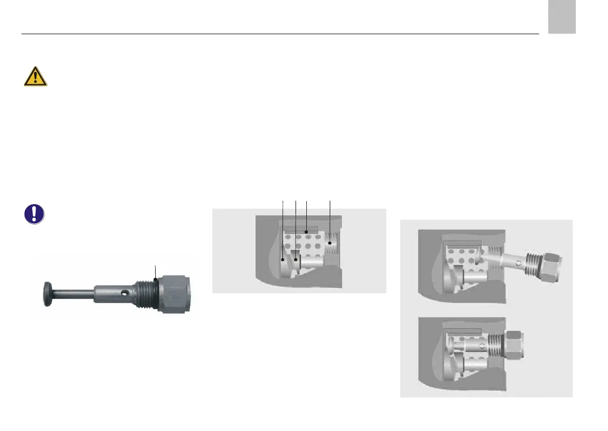
The pump elements are fitted only with O-
ring 15.4x2.1 (1) without any additional
sealing ring.
Fig.25. Pump element with O-ring (item 1)
Install the pump elements as follows:
Step 1:
Remove screw plug (if present).
Step 2:
Remove bothersome lubricant between the internal
thread, guide slot in the strainer ring and the groove
between the cam disc and return disc with a suitable
tool.
Fig.26. Sectional top view of pump housing
1 Internal thread
2 Guide slot in strainer ring
3 Cam disc
4 Return disc
Step 3:
Pull piston of the pump element as far as possible
out of the element, and insert it along the guide slot
of the strainer ring between the cam disc and return
disc ( Fig.27). If the pump element has not been
correctly installed, it is not possible to tighten the
thread.
Close any outlets which are not required with a
screw plug according to DIN 910-M18x1.5-5.8 with
sealing ring according to DIN 7603-A18x24-Al.
Fig.27. Inserting the pump element

 Loading...