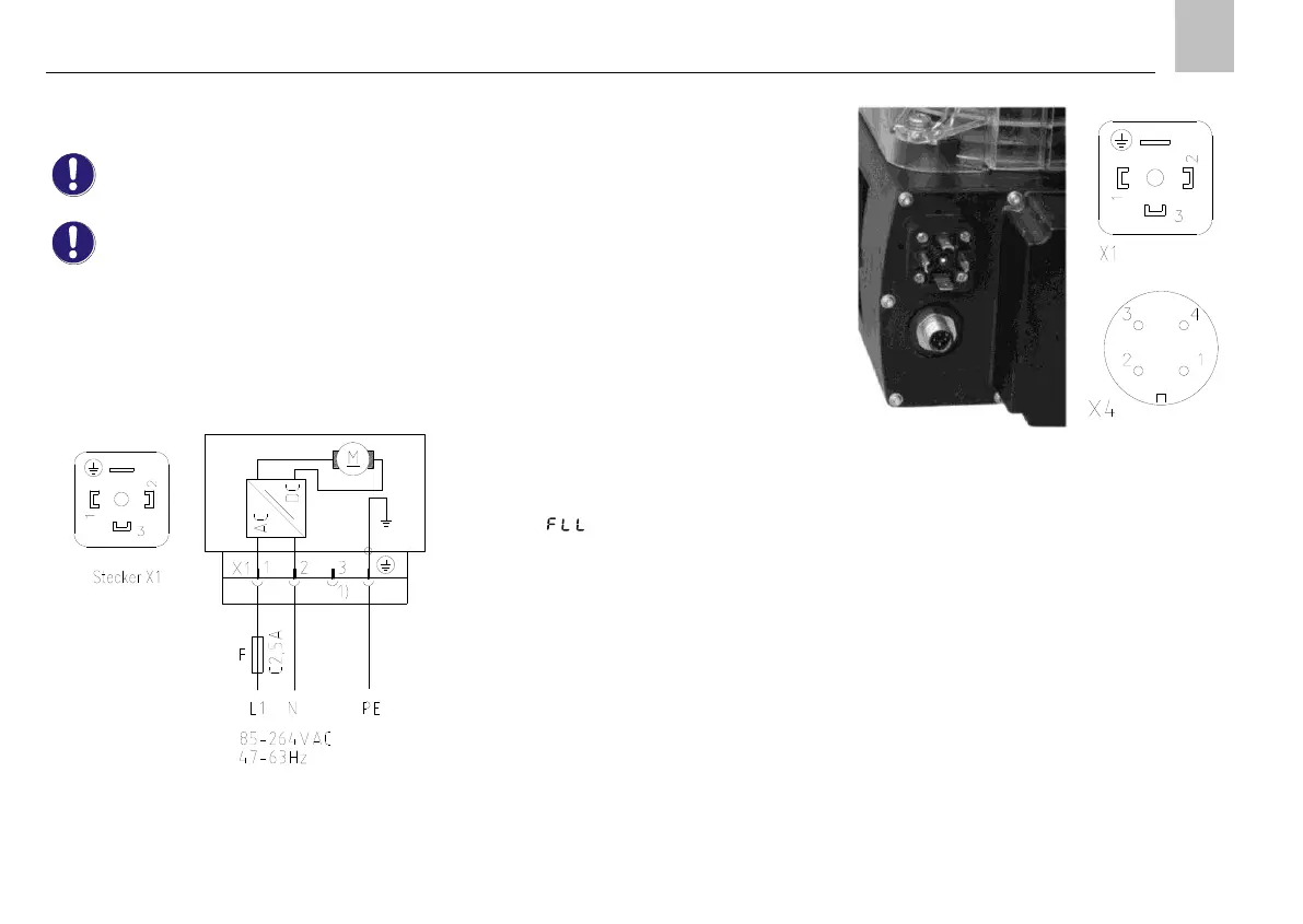
4.4.7. KFAS10, KFAS10-W (industrial)
Supply voltage 115/230 V AC, 50Hz and
60Hz
For voltage specifications, see the
rating plate of the piston pump unit and
Table 8.
X1 Electrical connection of plug according to DIN
175301-803.
Applies to all piston pump units of the
KFAS10 series.
Fig.20. Connection of KFAS10, KFAS10-W,
X1 Plug connector for supply voltage
1) PIN without internal connection
KFAS10
The piston pump unit is equipped with an X1 plug
connector and an M12x1 circular connector for cycle
switch monitoring.
o No internal fill level monitoring
o With cycle switch monitoring
o With SL2 fault signal output
KFAS10-W
The piston pump unit is equipped with an X1 plug
connector and an M12x1 circular connector for cycle
switch monitoring.
o With internal fill level monitoring.
Internal fill level monitoring is always active. If
the fill level reaches the "min." mark, the
operational sequence is stopped and the fault
message
appears on the screen.
o With cycle switch monitoring
o With SL2 fault signal output
Fig.21. KFAS10 and KFAS10-W plug connectors
Monitoring by an external cycle switch and the
output of a signal in case of malfunction are
performed via an M12x1 circular connector. 2-wire
and 3-wire cycle switches can be connected. See
illustrations Fig.22 to
Fig.24 for details about wiring.
 Loading...