4. Assembly instructions Page 21
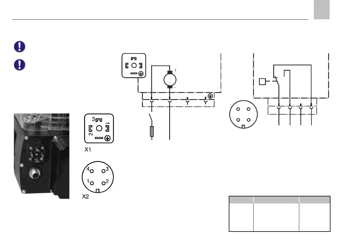
4.4.4. KFA1-M, KFA1-M-W (industrial)
Supply voltage 24 V DC
For voltage specifications, see the
rating plate of the piston pump unit and
Table 8.
X1 Electrical connection: Plug connector acc.
to DIN 175301-803.
X2 Signal output from fill level switch WS; M12x1
circular connector.
Fig.10. KFA1-M-W plug connector
KFA1-M without fill level monitoring
The piston pump unit possesses an X1 plug
connector.
1)
F 3 A
L+
24 V DC
M (OV, GND)
M
1
2
3
X1 1 2 3
5) 5)
KFA1-M
KFA1-M-W
Fig.11. X1 plug connector
1) External control unit;
relay contact "Pump ON"
5) PIN without internal connection
L+ + Supply voltage potential
(main machine switch ON)
M - Supply voltage potential
KFA1-M-W with fill level monitoring
The piston pump unit possesses an X1 and X2 plug
connector.
X2 1 2 3 4
BN
WH
BU
BK
+
MIN
5)
OK
24 V DC, max. 0,5 A
Q
WS
KFA1-M-W
1
2
4
3
Fig.12. X2 circular connector
WS Integrated fill level switch
Contact position shown: "filled reservoir",
i.e. contacts 1-4 open when the lubricant
quantity is insufficient
Table 14. Color coding
 Loading...