4. Assembly instructions Page 24
4.4.6. KFA10, KFA10-W (commercial
vehicles)
Supply voltage 115/230 V AC, 50Hz and
60Hz
For voltage specifications, see the
rating plate of the piston pump unit and
Table 8.
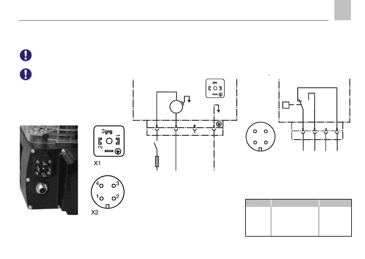
X1 Electrical connection: Plug connector acc.
to DIN 175301-803.
X2 Signal output from fill level switch WS; M12x1
circular connector.
Fig.17. KFA10-W plug connector
KFA10 without fill level monitoring
The piston pump unit only possesses one X1 plug
connector.
KFA10
KFA10-W
M
1~
1
2
3
X1 1 2 3
5)
1)
F 4 A
L1 N PE
115 or 230 V AC
50 or 60 Hz
Fig.18. X1 plug connector
1) External control unit;
relay contact "Pump ON"
5) PIN without internal connection
KFA10-W with fill level monitoring
The piston pump unit is equipped with an X1 plug
connector for the supply voltage and an M12x1 (X2)
circular connector for signal output from the fill level
switch (WS).
1
2
4
3
Q
X2 1
2
3 4
WS
BN
WH
BU
BK
+ MIN 5) OK
24 V DC, max. 0,5 A
KFA10-W
Fig.19. X2 circular connector
WS Integrated fill level switch
Contact position shown: "filled reservoir"
Table 16. Color coding

 Loading...