Page 15
EN
3. Overview
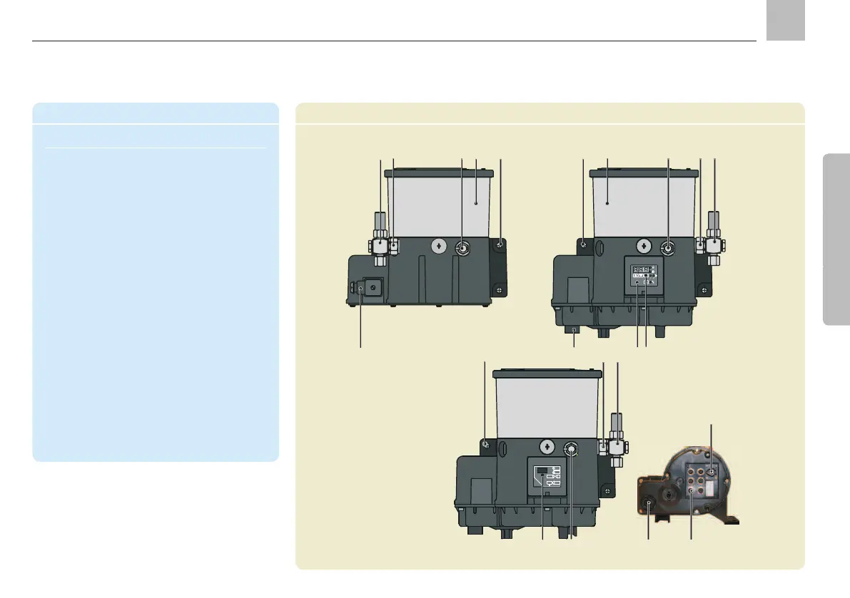
Components
Item Description Chapter
1 Assembly holes 4.2.1
2 Lubricant reservoir 4.2.2
3 Pump elements 4.3.
4 Pressure regulating valve 4.3.5
5 Conical head nipple 4.3.5
6 Electrical connection 4.5
7 General control unit/ Operating-
CAN bus display instructions
8 Pushbutton Operating
instructions
9 Inputs and outputs Operating
(CAN bus version) instructions
10 CAN bus plug Operating
instructions
BN
WH
BU
BK
BU
CS/PS
BN
X3
1
X2
2
3
4
+
SL2
1
2
3
4
1
2
3
4
X4
BU
BK
SL2
2,4W
179-990-700
1
2
3
CS/PS
Components
1
2
5
3
4
6
7
86
3
KFGC
(CAN-Bus)
KFGKFGS
1
5
2
1
5
4
3
6
9
10
4
7
without control
with control
with CAN bus control
Assembly instructions
KFGS
KFG
KFGC

 Loading...