Page 25
EN
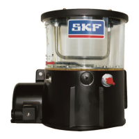
4.5.2 KFG series
The KFG pump unit is available in the voltage
designs 12 V DC and 24 V DC. The electrical
voltage connection is established through a
4-pin cable socket according to
DIN EN 175301-803.
Depending on the pump unit design, an addi-
-
grated into the pump housing.
The standard connections are presented below
(special designs may differ).
4.5.2.1 Power supply 12-/24 VDC
1
KFG...DC
23
X1
+
M
-
15
31
F
Connector pin assignment for 12/24 VDC
PIN Description
Pos. 1
(Mass) = 31
Pos. 2
(current) = 15 Supply
voltage potential
(ignition ON)
Cable socket per
DIN EN 175301-803
4.5.2.2 External control
The following control unit is designed
to control the lubrication and interval
times, as well as to monitor the lubrica-
tion process:
Order No. IG502-2-E
The operating instructions/functional
description of the control unit must
be observed.
about the control unit in brochure
Assembly instructions
KFG

 Loading...