EasyManuals Logo

SKF KFG Series User Manual

SKF KFG Series
100 pages
To Next Page IconTo Next Page
To Previous Page IconTo Previous Page
Page #32 background imageLoading...
Page #32 background image
Page 32
EN
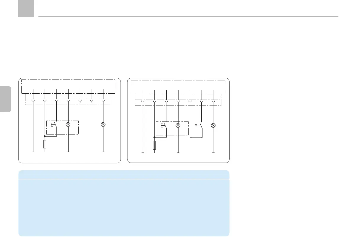
4.5.3.5 Connectivity for timer operation
without system monitoring
Connector pin assignment in timer operation
PIN Code Assignment
1 31 - Supply voltage potential (0 V, GND)
  
   
  
  
  
  
4.5.3.6 Connectivity for timer operation
with system monitoring
Programming: tPA, tCO, COP = OFF
1
BN
KFGS...
F
2 3 4 5 6 7
X1
RD-BK
BU
PK
VT-GN
DK
SL2
2,4 W
31 15
SL1
2,4 W
1
BN
KFGS...
F
2 3 4 5 6 7
X1
RD-BK
BU
PK
VT-GN
DK
SL2
2,4 W
SL1
2,4 W
BK
PS
+
31 15
YE (+)
Programming: tPA, tCO, COP = CS
Timer mode
In timer mode, the interval time is determined

time value in hours.

value in minutes.

internally connected to the integrated pump
control unit. A fault signal can be sent to the
vehicle control/electronics system via indicator
light SL2.
Assembly instructions
KFGS

Other manuals for SKF KFG Series

Questions and Answers:

Question and Answer IconNeed help?

Do you have a question about the SKF KFG Series and is the answer not in the manual?

SKF KFG Series Specifications

General IconGeneral
BrandSKF
ModelKFG Series
CategoryWater Pump
LanguageEnglish

Related product manuals