Page 35
EN
3V2V1
1
1
1
1
1
1
2
2
2
2
2
2
3
3
3
3
3
3
4
4
4
4
4
4
1
2
3
4
1
2
2
1
2
1
2
1
1
2
3
4
1
2
3
4
1
2
3
4
A B C
1 2
3
4
5 6
7
X1
BN
RD-BK
BU
PK
BK
BK
VT-GN
CAN-BUS
M12x1
1x21M1x21M
M12x1
1x21M1x21M
M12x1
1x21M1x21M
M12x1
F1
S1
M L
31 30
15
CS4 (MC)
V4
SL2
RD
CS1
CS1
CS2
CS2
CS3
CS3
V1 V2 V3
+++++++ + +
–– – – –
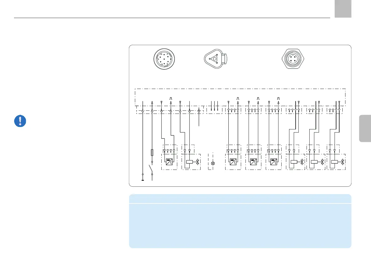
4.5.4.2 Connectivity
Example of connecting four reversing valves
and four piston detectors on devices with the
maximum equipment level (6x M12x1 round
plug-in connections) for operating a progres-
sive feeder system, distributed in four lubrica-
tion zones
A
B
C
CS.. = Piston detectors V.. = Reversing valves
2
4
5
3
1
6
7
34
1 2
Assignment of
round 7-pin plug
Assignment of
M12x1 4-pin round plug
possible.
Legend for connection illustration with maximum equipment level
CS1 – CS4 Piston detectors 1 - 4 V1 - V4 Valves 1 – 4
MC Machine contact SL2
L+ + Supply voltage potential be operated in place of valve 4)
S1 Ignition switch F1 Fuse
Assignment of
CAN bus plug
Assembly instructions
KFGC

 Loading...