Page 36
EN
1
2
3
4
1
2
B C
1 2 3 4 567
X1
BN
RD-BK
BU
PK
BK
BK
VT-GN
CAN-BUS
M12x1
F1
S1
M L+
31 30
15
CS4 (MC)
V4
SL2
RD
KFGS...-...B...
+ + +
––
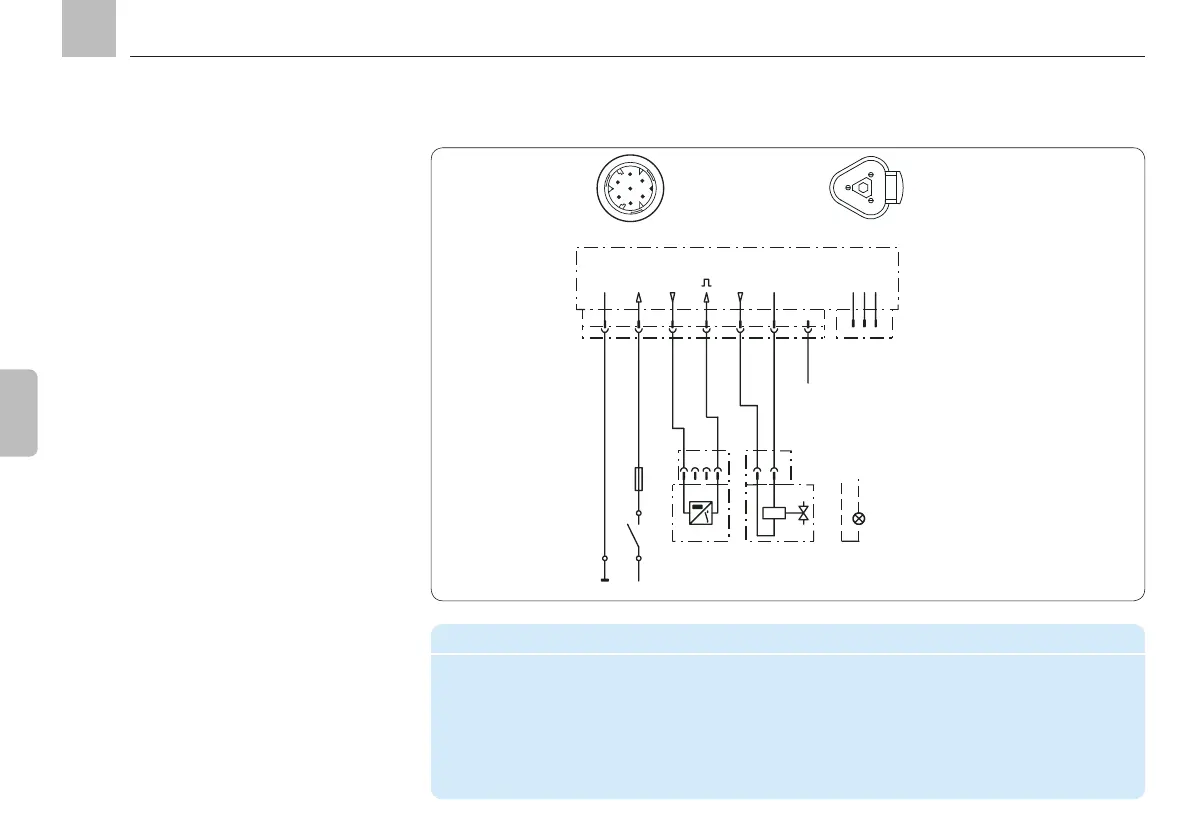
Example of connecting a piston detector or
machine contact and a reversing valve to a
device with minimum equipment level (without
M12x1 circular connectors) for operating a
progressive feeder system, multiple zones not
used.
Piston detector
Assignment of the 7-pin round plug
2
4
5
3
1
6
7
A
B
C
Legend for connection illustration with minimum equipment level
CS4 Piston detector 4 V4 Valve 4
MC Machine contact SL2
L+ + Supply voltage potential be operated in place of valve 4)
S1 Switch F1 Fuse
CAN bus plug assignment
V.. = Reversing valves
Assembly instructions
KFGC

 Loading...