It is the responsibility of the operator to read, completely understand and follow all instructions and warnings
contained in this operating manual and on the aerial platform.
FAMILIARIZATION
2.2 Component Identification
The following descriptions are for identification,
explanation and locating purposes only.
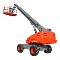
2.2-1 Drive Bypass Valve
This valve is located on the inboard side of the drive
pump and can be identied with a yellow paint mark
on it.
1
Figure 2-1. Drive Bypass Valve
1. Drive Bypass Valve with Override Stems
- This valve, when loosened two revolutions
counterclockwise, is used to override drive relief
valves so that the aerial platform can be loaded or
unloaded from a trailer using a winch line.
2.2-2 Main Power Disconnect Switch
This switch is located in the engine compartment near
the battery.
1
Figure 2-2. Main Power Disconnect Switch
1. Main Power Disconnect Switch - This switch,
when in “ ” off position, disconnects power to
all circuits. Switch must be in “ ” on position to
operate any circuit. Turn switch “ ” off when
transporting aerial platform.
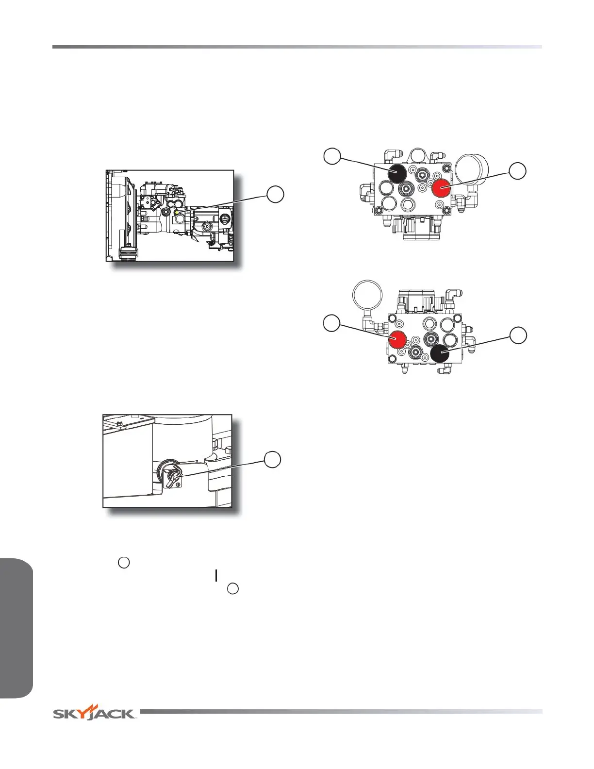
2.2-3 Brake System
The brake system is located in the control compartment.
The brakes must be manually disengaged before
pushing, winching or towing. Refer to Section 2.5-1
for procedure on how to release brakes manually. The
system contains the following controls:
1
2
Figure 2-3a. Brake System - SJ40/45T
2
1
Figure 2-3b. Brake System - SJ61/66T
1. Brake Hand Pump
2. Brake Auto Reset Valve Plunger
Page 14
SJ 40T & SJ 45T
SJ 61T & SJ 66T
Control Functions Section 2 - Familiarization