Page 4
1. Spool Valve -Pushed to the right by electric
solenoid. This opens the internal oil pressure galley
allowing the fluid to go through the check valve and
on to the cylinder. Also, the spool valve opens the
oil return line providing an oil path through the
internal oil galley back to the reservoir.
2. Pilot Plunger Valve - Right pilot plunger valve
is pushed up by the incoming oil pressure mechani-
cally opening the check valve located above it in
the return circuit. This action allows the oil from the
right side of the slave cylinder to go back into the
reservoir. The left pilot plunger valve is not affected
in this operation mode.
3. Check Valves - Both check valves are
opened in this operation mode. The left valve is
pushed open by the oil pressure created by the
pump. The oil then continues to go through the
lines and pushes the slave cylinder piston to the
right. At the same time, the right check valve is held
open mechanically by the pilot plunger providing a
return path for the oil through the mini-valve back to
the reservoir.
4. Speed Adjustment - The left speed control
(output side) does not have any effect in this oper-
ation mode because the oil is routed around the
speed adjustment through a by-pass valve and
then to the output port. The right speed adjustment
controls the speed of the table function by restrict-
ing the amount of oil going back to the reservoir.
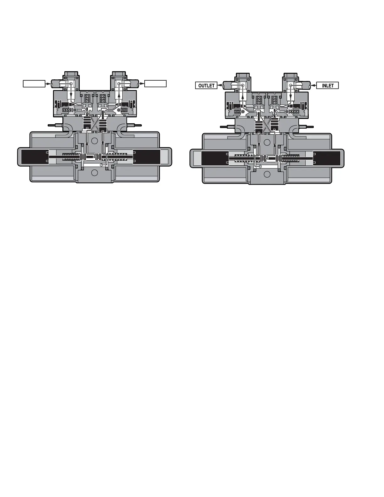
e. Mini-Valve Right Port Activated
(See figure 1-6)
Slave Cylinder Piston Moves to Left
Right Mini-Valve Port is Supply Line
Left Mini-Valve Port is Return Line
f. Mini-Valve Left Port Activated
(See figure 1-7.)
Slave Cylinder Piston Moves to Right
Left Mini-Valve Port is Supply Line
Right Mini-Valve Port is Return Line
1. Spool Valve - Pushed to the left by electric
solenoid. This opens the internal oil pressure gal-
ley allowing the fluid to go through the check valve
and on to the cylinder. Also, the spool valve opens
the oil return line providing an oil path through the
internal oil galley back to the reservoir.
2. Pilot Plunger Valve - Left pilot plunger valve
is pushed up by the incoming oil pressure mechani-
cally opening the check valve located above it in
the return circuit. This action allows the oil from the
left side of the slave cylinder to go back into the
reservoir. The right pilot plunger valve is not
affected in this operation mode.
3. Check Valves - Both check valves are
opened in this operation mode. The right check
valve is pushed open by the oil pressure created by
the pump. The oil then continues to go through the
lines and pushes the slave cylinder piston to the
left. At the same time, the left check valve is held
open mechanically by the pilot plunger providing a
return path for the oil through the mini-valve back to
the reservoir.
4. Speed Adjustment - The right speed control
(output side) does not have any effect in this
operation mode because the oil is routed around
the speed adjustment through a by-pass valve and
then to the output port. The left speed adjustment
controls the speed of the table function by restrict-
ing the amount of oil going back into the reservoir.
Figure 1-7 Mini-Valve Left Port ActivatedFigure 1-6. Mini-Valve Right Port Activated
INLET OUTLET

 Loading...


