Page 12
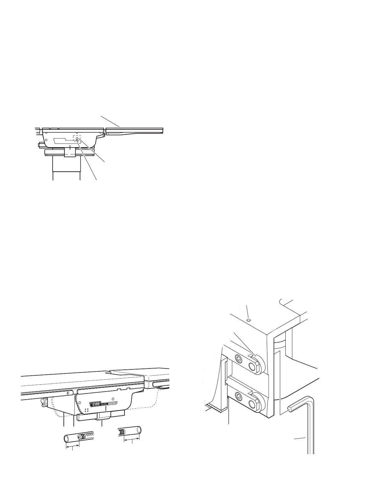
LEG SECTION
SET SCREW
LEG SECTION CYLINDER
ECCENTRIC CAM
To adjust:
Loosen the cam locking set screws located on the
bottom of the cylinder mounting plates inside the
table side frames. Use an allen wrench to turn the
cylinder eccentric cams as required to shift either
cylinder fore or aft as needed so no twisting or
flexing of the leg section is observed when it is
stalled in the horizontal position. Tighten set screws
when proper adjustment is achieved. See figure 2-
3.
Figure 2-3. Leg Section Adjustment
c. Slide and Kidney Lift Cylinders
If the Slide or Kidney Lift cylinder has been re-
moved, the distance from the end of the piston to
the end of the cylinder housing must be checked to
make sure the functions will operate correctly.
With table top centered, the distance from the end
of the Slide piston to end of cylinder is:
Head End - 82 mm Foot End - 120 mm
The table top should slide 7-1/2" toward the head
and 13-1/4" toward the foot when positioned prop-
erly. Refer to figure 2-4.
With Kidney Lift all the way down, the distance
from the end of the Kidney Lift piston to end of
cylinder is:
Head End - 82 mm Tail End - 11 mm
Figure 2-4.
2-3. Slide Roller Adjustment
The pivot pins on the slide rollers are eccentric
cams. The rollers can be adjusted if required to
maintain proper top slide operation.
NOTE
During Trendelenburg positioning, top
slide movement of up to 1/2" can be
considered normal due to gear lash.
To adjust:
Remove the Seat section top, the hose cover and
the right and left lateral tilt frame covers for access
to the top rollers.
1. Align the table top so the rollers to be
adjusted are contacting the slide bars.
2. Loosen the adjustment cam set screw and
adjust the roller using an 8mm Allen wrench. See
figure 2-5. To avoid any possible binding in the slide
mechanism, adjust the roller on the opposite side of
the table in the same manner (cam turned toward
same end of table on each side).
3. Adjust rollers so top slides smoothly with no
up or down movement of the table top.
4. When adjustment is complete, tighten set
screws, replace covers and top section.
Figure 2-5.
82mm
120mm
7-1/2"
SLIDE
TOWARD
HEAD
13-1/4"
SLIDE
TOWARD
FOOT
SLIDE
ROLLER
8mm
ALLEN
WRENCH
SET SCREW

 Loading...


