Page 53
CS-5
NS-6
NS-7
CS-3
CS-2
CS-1
NS-1
NS-4
NS-3
NS-2
CN10
CS-4
NS-5
TS-1 TS-2
NS-1 TREND
NS-2 REV. TREND
NS-3 TILT LEFT
NS-4 TILT RIGHT
NS-5 BACK - DOWN TO LEVEL /SLIDE INHIBIT
NS-6 BACK - UP TO LEVEL
NS-7 LEG - DOWN TO LEVEL
CS-1 SLIDE/LEG DOWN INHIBIT
CS-2 SLIDE/BACK DOWN INHIBIT
CS-3 KIDNEY/BACK 45˚ UP INHIBIT
CS-4 LEG DOWN 45˚/SLIDE INHIBIT
CS-5 BACK UP 45˚/KIDNEY UP INHIBIT
RELAY BOX
2. The meter should read 1 to 2 ohms at room
temperature.
3. Measure the resistance between either pin
and ground.
4. Meter should read infinity.
d. Test Results:
If you do not receive the correct meter readings, the
motor or wiring is defective.
6-13. Return-to-Level Micro-Switches.
The return-to-level system for the Model 3500B is
the same as non-battery models except for the
wiring and connection to the relay box.
The return-to-level feature is activated by a single
button on the pendant control and automatically
levels the major table functions, lateral tilt, tren-
delenburg, flex, back section, and leg section.
The kidney lift has a back section-up inhibit switch
to prevent the table back section from damaging
the kidney lift when the lift is raised. The back
section still has the capability to be lowered and
raised, but will not raise more than 45° above
horizontal until the kidney lift is completely down. If
the back section is raised more than 45° above
horizontal, the system will not allow the kidney lift to
be raised.
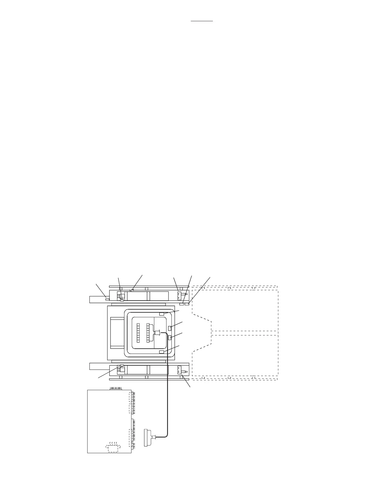
Figure 6-23.
The slide function has inhibit switches to prevent
damage to the back and leg sections. If the back
section is below horizontal the top will not slide
toward the foot end. If the leg section is lowered
more than 45° below horizontal the top will not slide
toward the head end. Likewise, if the top is slid
toward the foot end, the back section will not go
below horizontal. If the top is slid toward the head
end, the leg section will not go more than 45° below
horizontal.
The return-to-level/inhibit system consists of 12
micro-switches, an electrical connector, 2 terminal
strips and the related wiring. The micro-switches
are mounted on or adjacent to the function they
control and are wired for normally open or normally
closed operation. The micro-switches are cam or
lever actuated and can be adjusted at the individual
switch mounting brackets. See figure 6-23.
The micro-switches operate on low voltage, and
control the function circuits (pump/motor and ap-
propriate solenoid valves) when activated by the
pendant control RETURN button.
The micro-switches are wired to the relay box
through 2 terminal strips, a riser cord and the 15 pin
connector CN10. See figure 6-23 for switch loca-
tion and identification.
3500B

 Loading...


