Page 29
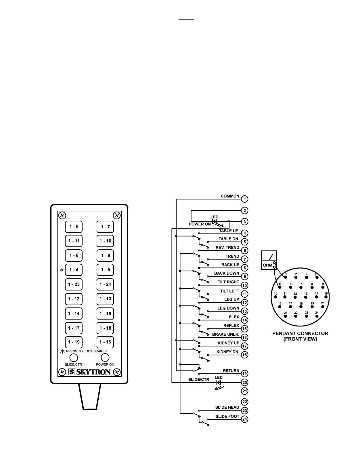
Figure 5-3. Pendant Control Test
b. Test Results
If you do not receive the correct voltage measure-
ment, the problem would have to be in the wires,
main switch, fuses, or power cord. If the correct
voltage is obtained, everything is good up to this
point and the problem would have to be in another
area.
5-3. Pendant Control
The Pendant Control consists of 18 micro-switches
(buttons). When any of the circuits are completed
(by depressing a control button) the appropriate
relay contacts (located in the relay box) close
applying 120V potential to the appropriate solenoid
to operate the mini-valve and the pump/motor. The
Pendant Control has only 5-6 volts applied to it.
a. Pendant Control Test
The following test will determine if the micro-switches
inside the Pendant Control are function-ing cor-
rectly.
1. Unplug the pendant control from the base of
the table. You will be checking the cord side
connector.
2. Use an ohmmeter R x 1 scale and check the
continuity between pin 1 and pins 4 through 24.
See figure 5-3.
3. Ohmmeter must show continuity between the
pins that are indicated when the appropriate but-
tons are pressed.
3500
NOTE
Pins 2 and 3 are connected to the green
LED (power ON light on the pendant
control) and pin 20 is connected to the
amber LED (slide center light on the
pendant control) these pins cannot be
checked with an ohmmeter.

 Loading...


