Page 46
6-6. Switch-Over Relay
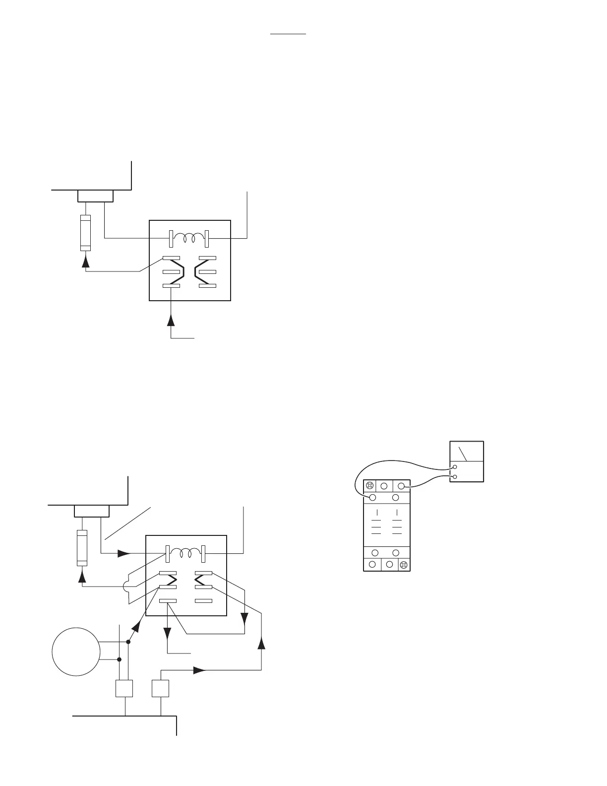
a. Switch-Over Relay in OFF Position
The Switch-Over Relay supplies the 24 volt input
power from either the BATTERY or AC120V oper-
ating modes to the relay box for table operation. In
the normal OFF position, BATTERY power is sup-
plied to the relay box. See figure 6-8.
NOTE
The battery charging circuit is only op-
erational when the table is in the AC120V
operating mode.
c. Switch-Over Relay Test
Using a DC voltmeter, test the operation of the relay
in both the OFF (AC120V - OFF) and Activated
(AC120V - ON) positions. See figure 6-10.
NOTE
The Switch-Over Relay mounting block
may have to be removed from the base
for test access.
OFF: (AC120V - OFF)
term. 7(-) and term. 1(+) = 24 to 28VDC
term. 7(-) and term. 6(+) = 0VDC
Activated: (AC120V - ON)
term. 7(-) and term. 6(+) = 26.5±1VDC
3500B
Figure 6-8. Relay in OFF Position
BATTERY
(+)
S-O RELAY
2
1
3
4
6
8
5
7
RELAY BOX
CN4
FUSE
15A
(-)
b. Switch-Over Relay in Activated Position
When the AC120V mode is activated by the main
switch, a signal from the relay box activates the
Switch-Over Relay. The relay then supplies the
AC operating mode output power to the relay box
and also activates the battery charging circuit. See
figure 6-9.
Figure 6-9. Relay in Activated Position
BATTERY
(+)
S-O RELAY
RELAY BOX
SIGNAL OUT
2
6
8
5
3
1
4
7
RELAY BOX
CN4
CN14
CAPACITOR
CHARGING
BOX
CN51
FUSE
15A
(-)
Figure 6-10. Switch-Over Relay
DCV
2
1
3
45
6
8
7

 Loading...


