Page 36
The micro-switches operate on low voltage, and
control the function circuits (pump/motor and ap-
propriate solenoid valves) when activated by the
pendant control RETURN button.
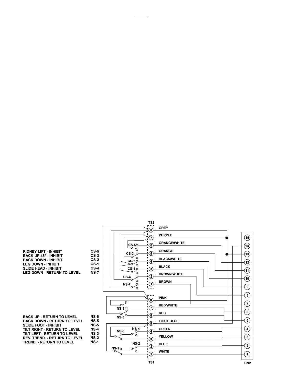
The micro-switches are wired to the relay box
through 2 terminal strips, a riser cord and the 15 pin
connector CN2. See figure 5-12 for switch location
and identification.
5-8. Return/Inhibit System Troubleshooting
If a problem is suspected in the return circuits,
disconnect the connector CN2 from the Relay Box
to eliminate the circuits. Ensure that all table
functions operate properly using the Pendant Con-
trol. If the functions do not work properly using the
Pendant Control, refer to the appropriate test sec-
tion and make all needed repairs before working on
the return circuits.
NOTE
It is normal for the back section to move
up if the RETURN button is pushed
when connector CN2 is disconnected
from the relay box.
All of the micro-switches are connected to the relay
box via a wiring harness and the micro-switch riser
cord from terminal strips 1 and 2 to connector CN2.
The terminal strips are located under the hose
cover on the top of the elevation column. Connector
CN2 plugs into the relay box and is the most
convenient location to make circuit continuity
checks. See fig. 5-13 for connector pin locations.
a. Switch Test
Turn Main Power ON, lock the table brakes, and
place the table top sections in a level position with
the Kidney Lift down. Disconnect connector CN2
from the relay box and using an ohmmeter, test the
wiring and switch operation at the appropriate pin
numbers for the micro-switch in question as shown
in figures 5-14 through 5-21.
NOTE
Be sure to isolate the circuit when mak-
ing continuity checks.
NOTE
If you do not receive the proper continu-
ity results at connector CN2 it does not
necessarily mean the micro-switch is
defective. There could be a problem
with the riser cord between connector
CN2 and terminal strips 1 and 2, or in
the wiring from the switch to the terminal
strips. Further tests will have to be
made to determine the exact problem.
Figure 5-13. Return / Inhibit Micro-Switch Test
3500

 Loading...


