Page 44
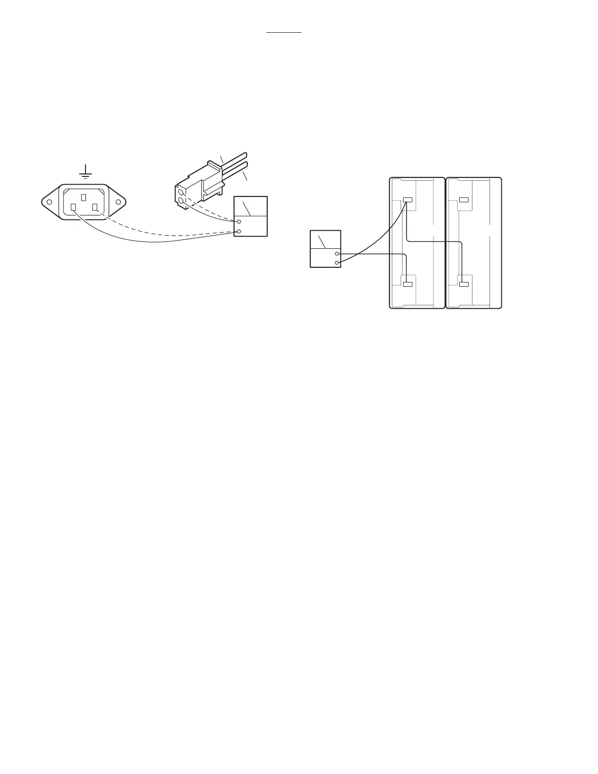
Check the continuity from the power cord connec-
tor ICN1, through the fuses, switch and wiring to
connector CN12. Remove the power cord, discon-
nect CN12 (black and white wires), and test as
shown in figure 6-3.
4. Continue to press the TABLE UP button on
the pendant control so that the pump motor contin-
ues to run and using a DC voltmeter, check the
voltage drop of each battery individually. See figure
6-4.
5. Meter should read 12VDC ± 1VDC.
3500B
6-4. Batteries
The BATTERY operating mode is powered by two
12 volt batteries connected in series to provide the
24 volt operating power.
The battery system voltage should be 24VDC at a
range of 22VDC to 26VDC. If the battery charge
level falls below 23.5 volts the BATTERY operation
indicator on the pendant control will blink indicating
that the batteries require recharging. The built-in
charging system automatically keeps the batteries
at the proper charge level when the AC120V oper-
ating mode is ON. The charging system will
operate while the table is being operated in the
AC120V mode.
a. Battery System Test
1. Disconnect the main power cord and using
a DC voltmeter, test each individual battery at its
terminals. Meter should read 12VDC ± 1V.
2. To accurately test the batteries, they must
be tested under a full load. Disconnect the main
power cord and make sure all other connectors are
connected.
3. Turn BATTERY power ON and elevate the
table to its full up position.
Figure 6-3. CN12 to ICN1 Continuity Test
OHM
BLACK
CN12
TO GROUND
ICN1
2
1
N
L
WHITE
b. Test Results
A reading of 11 volts or below indicates the battery
needs charging.
After batteries have been fully charged, repeat the
full load test. If either battery's voltage drops below
11VDC it should be replaced.
6-5. Battery Charging Box/AC120V
Transformer
The Battery Charging Box contains the battery
charging system as well as the components for
AC120V operation (except the transformer).
a. Transformer Test
1. Confirm 120VAC input at CN12 using Main
Switch test in 6-3a.
2. Connect CN12, disconnect CN13 (brown
and red wires) and using an AC voltmeter, test the
transformer output at CN13. See figure 6-5.
3. Meter should read 22VAC.
Figure 6-4.
DCV
BATT 1 BATT 1

 Loading...


