Page 48
6-8. Auxiliary Switches
The following tests will determine if the auxiliary
switches are functioning properly.
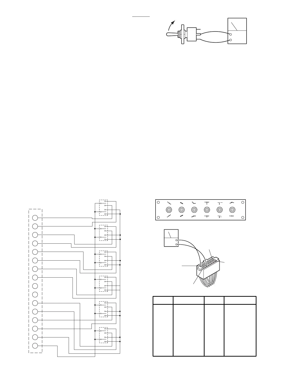
a. Switch Test
Disconnect connector CN3 at the Relay Box and
using an ohmmeter check for continuity at the
connector pins (pin 1A common) while activating
the appropriate switch. See figure 6-13. Meter
should read 0 ohms.
b. Test Results
If proper meter readings are not received, test the
individual switches as necessary. Using an ohm-
meter, test the operation of an individual switch with
the (+) test lead at the center terminal of the switch
and the (-) test lead at the terminal opposite the
direction of the switch actuation. See figure 6-14.
Meter should read 0 ohms. If the switches check
out, the problem would have to be in the wires or
connector CN3.
3500B
Figure 6-13. Auxiliary Switch Connector CN3
6-9. Relay Box
The power supply is directly connected to the relay
contacts. When these contacts are closed, 24
volts is supplied to the solenoids which are mounted
on the hydraulic mini-valves. One relay is used to
supply power to the pump/motor and is always
activated no matter what control function is se-
lected. The brake locking circuit relay is also
activated when any control function other than
BRAKE UNLOCK is
initially
selected.
Also, inside the 3500B relay box is a step-down
transformer and full-wave rectifier which decreases
the voltage to 5-6 volts. This low voltage potential
controls the relays by the use of the hand-held
pendant control buttons. Basically the relays en-
able a 5-6 volt potential to control the 24 volt circuit.
The following tests will determine if the relay box is
functioning correctly.
2 (B1)
1 (A1)
15 (A8)
16 (B8)
CN8
OHM
PIN NO
1 (A1)
2 (B1)
3 (A2)
4 (B2)
5 (A3)
6 (B3)
7 (A4)
8 (B4)
Red
White/Red
Brown
Yellow
Orange
White/Orange
White/Brown
Blue/White
9 (A5)
10 (B5)
11 (A6)
12 (B6)
13 (A7)
14 (B7)
15 (A8)
16 (B8)
--
--
White/Purple
Purple
Grey
White/Grey
Red/White
Pink
COLOR
PIN NO COLOR
1
SW1
CN3
TABLE UP
TABLE DOWN
HEAD DOWN
HEAD UP
RIGHT DOWN
LEFT DOWN
BACK UP
BACK DOWN
KIDNEY DOWN
KIDNEY UP
LEG UP
LEG DOWN
PUMP MOTOR
+24V
SW2
SW3
SW4
SW5
SW6
2
3
4
5
6
7
8
9
10
11
12
13
14
15
16
B8/B2 B8/A3 B8/A4 B8/A1 B8/A7 B8/B6
B8/A2 B8/B3 B8/B4 B8/B1 B8/B7 B8/A6
OHM
Figure 6-14. Auxiliary Switch Test

 Loading...


