Page 1
SECTION I HYDRAULIC SYSTEM
1-1. General
Electro-Hydraulic System
The hydraulic system (with the exception of the
hydraulic cylinders and hoses) is contained within
the base of the table. The hydraulic valves and
pump are electrically controlled by the use of a
hand-held push button pendant control. The power
requirements for the table are 120 VAC, 5 amp, 60
Hz.
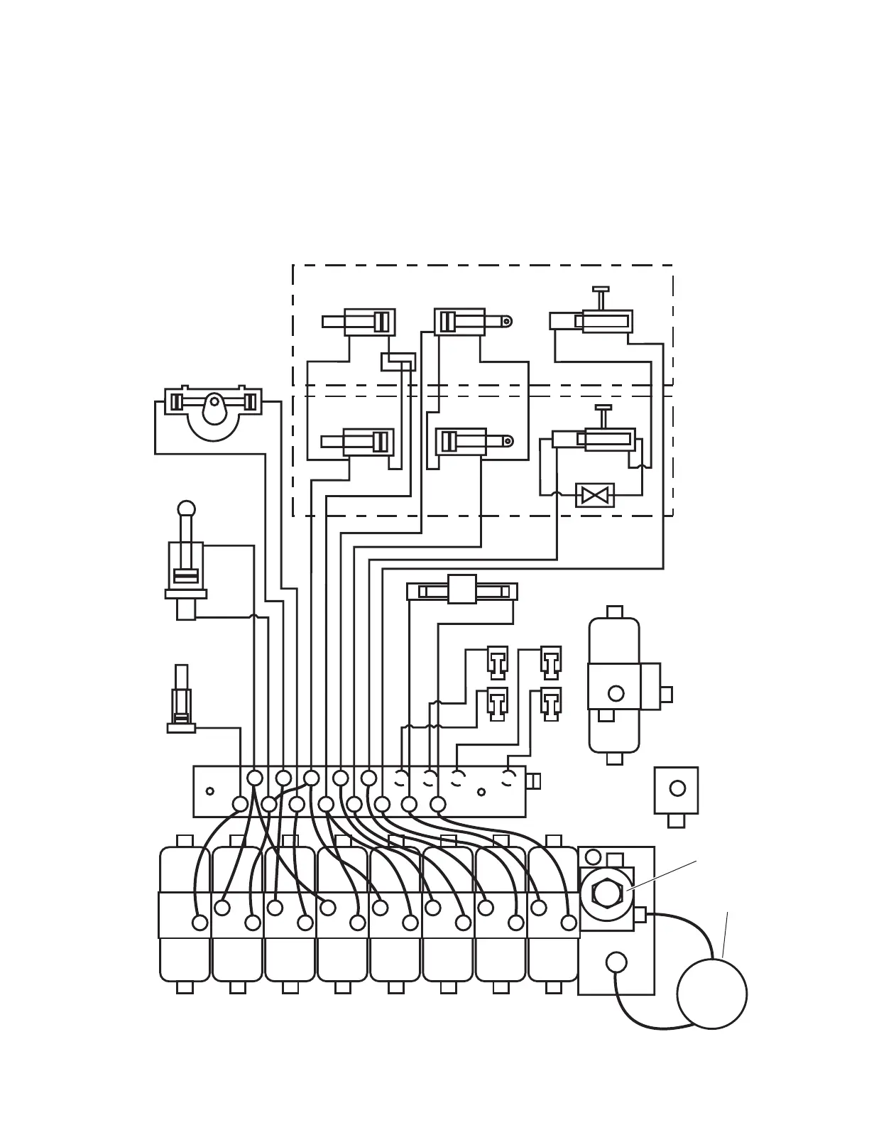
The table contains the following components. Re-
fer to the block diagram (figure 1-1) for relationship.
Figure 1-1. Hydraulic Block Diagram
ELEV TREND TILT FLEX BACK LEG KIDNEY SLIDE
MOTOR/PUMP
ASSEMBLY
MINI-VALVES
PRESSURE
RELIEF VALVE
EMERGENCY
BRAKE
RELEASE
BRAKE
BRAKE SYSTEM
SLIDE
PLUMBING
TERMINAL
ELEVATION
TREND
TILT
BACK
BACK
LEG KIDNEY
KIDNEY
LEFT
SIDE
FRAME
RIGHT
SIDE
FRAME
LEG
2
4
6
8
10
1
3
5
9111213
7

 Loading...


