Page 47
6-7. Pendant Control
The Pendant Control is part of the solid state,
multiplex, logic control system. The pendant con-
trol contains illuminated, circuit board mounted
switches and a micro processor. The encoded
output from the pendant control is serial bit stream
logic.
The output signal is transmitted to the micro pro-
cessors in the relay box where the logic is decoded
and the appropriate relays for the selected function
are activated.
Pendant Control troubleshooting should begin by
switching the operating mode of the table. For
example; if a function fails when attempting to
operate the table in the AC120V mode, switch to the
BATTERY mode. If the function now operates, the
problem is not the pendant control and probably is
a problem located between the power cord and the
relay box. If the function also fails when in battery
operation, use the auxiliary switches to operate the
function. If the function now operates, the problem
is probably in the pendant control, connectors or
wiring from the pendant control to the relay box.
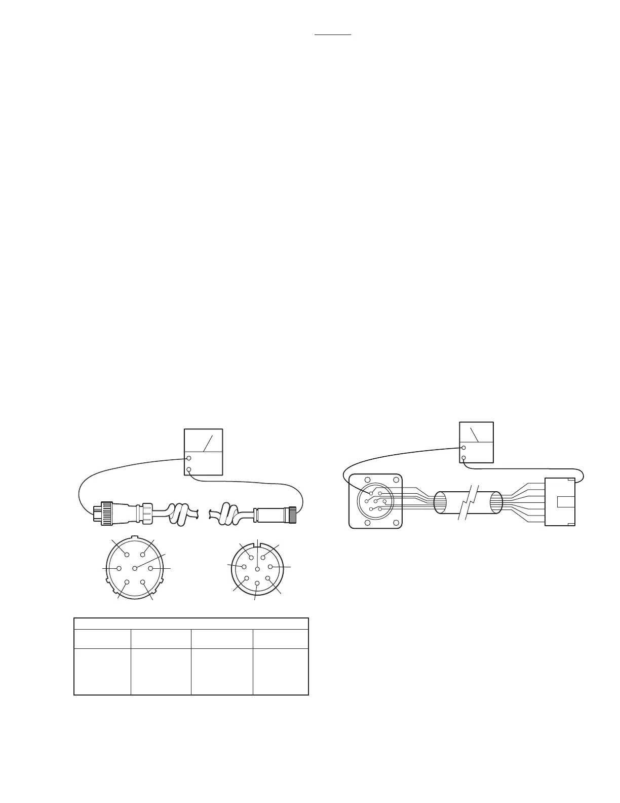
3500B
Figure 6-11. Pendant Control Cord Test
a. Pendant Control Test
There are no servicable components within the
Pendant Control. The cord is detachable and can
be tested for continuity between the pins on the
connectors. Use the following procedure to test the
pendant control cord.
Disconnect the cord from the base connector and
from the pendant control connector and using an
ohmmeter, test the continuity between the corre-
sponding pins in the connectors. See figure 6-11.
b. Test Results
If you do not receive the correct readings, the
wiring or connector pins may be faulty.
c. Base Connector Test
If correct readings are received, test the wiring from
the base connector to connector CN7 at the Relay
Box. Disconnect connector CN7 from the Relay
Box and using an ohmmeter, test the continuity
between the corresponding pins in connectors
CN7 and the base connector. See figure 6-12.
Figure 6-12. Base Connector Continuity Test
OHM
BASE
CONNECTOR
CN7
1
34
6
7
5
2
1
2
3
4
5
6
7
OHM
1
A
C
B
D
E
F
Test Leads
Base Conn.
Pin
1
2
3
4
A
B
C
D
5
6
7
E
F
G
Pend. Conn.
Pin
Base Conn.
Pin
Pend. Conn.
Pin
G
H
3
4
5
2
6
7
If the correct readings are obtained, this part of the
circuit is okay and the problem may be Pendant
Control or the Relay Box. Contact SKYTRON if all
tests performed indicate that the problem is located
in the Pendant Control.

 Loading...


